
Nasal cannula with reduced heat loss to reduce rainout

a technology of heat loss reduction and nasal cannula, which is applied in the direction of respirators, lighting and heating apparatus, combustion types, etc., can solve the problems of excessive condensation, respiratory irritation, and discomfort of patients, and achieve the effect of reducing the temperature gradient of the heated and humidified gas

Active Publication Date: 2012-05-08
BRIDGE BANK NAT ASSOC
View PDF33 Cites 21 Cited by
  • Summary
  • Abstract
  • Description
  • Claims
  • Application Information

AI Technical Summary

Benefits of technology

[0007]Also, the present invention provides a method of reducing heat loss and rainout in a nasal cannula comprising the steps of generating heated and humidified gas and flowing the heated and humidified gas toward a nasal passage of a patient through a single conduit having an upstream inner diameter of the single conduit and a downstream inner diameter smaller than the upstream inner diameter.
[0009]The present invention further provides a method of delivering heated and humidified gas to a patient comprising the steps of generating heated and humidified gas; flowing the heated and humidified gas toward a nasal passage of a patient through a conduit; and disposing the conduit against the skin of the patient, thereby reducing a temperature gradient of the heated and humidified gas along the conduit

Problems solved by technology

Delivery of oxygen and oxygen-enriched air to the respiratory tract of a patient can result in discomfort to the patient, especially when the air is delivered over an extended period of time.
Delivery of air having relatively low absolute humidity can also result in respiratory irritation.
When heating and humidifying a breathing gas for breathing through a nasal cannula, any cooling in the nasal cannula may lead to excessive condensation within the nasal cannula.

Method used


Image

  • Nasal cannula with reduced heat loss to reduce rainout
  • Nasal cannula with reduced heat loss to reduce rainout
  • Nasal cannula with reduced heat loss to reduce rainout

Examples


Embodiment Construction

[0032]Certain terminology is used herein for convenience only and is not to be taken as a limitation on the present invention. The terminology includes the words specifically mentioned, derivatives thereof and words of similar import. As used herein, the term “proximal” is defined to mean a direction closer to the humidification cartridge described herein and “distal” is defined to mean a direction farther from the humidification cartridge described herein. The following describes exemplary embodiments of the invention. However, it should be understood based on this disclosure, that the invention is not limited by the exemplary embodiments of the invention.

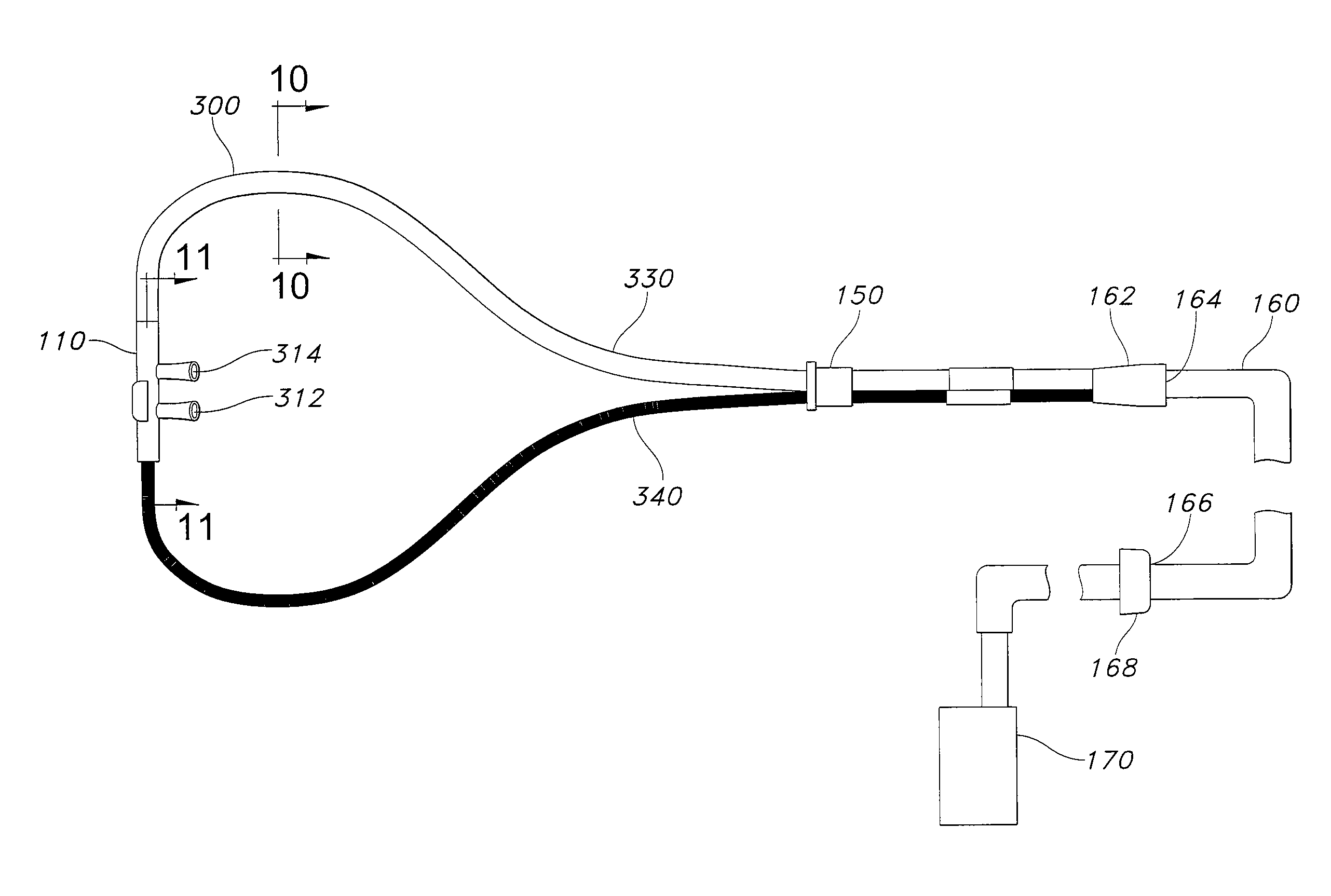
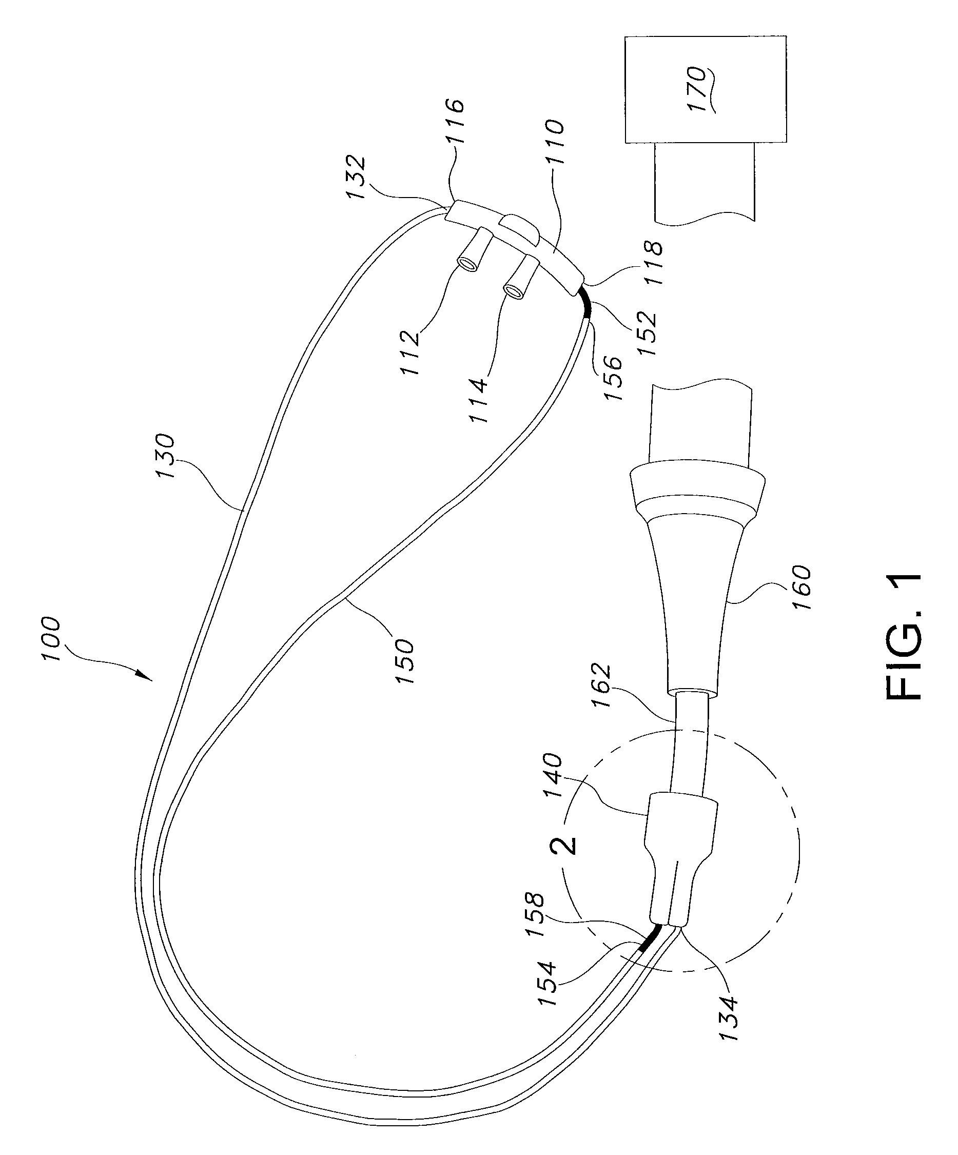
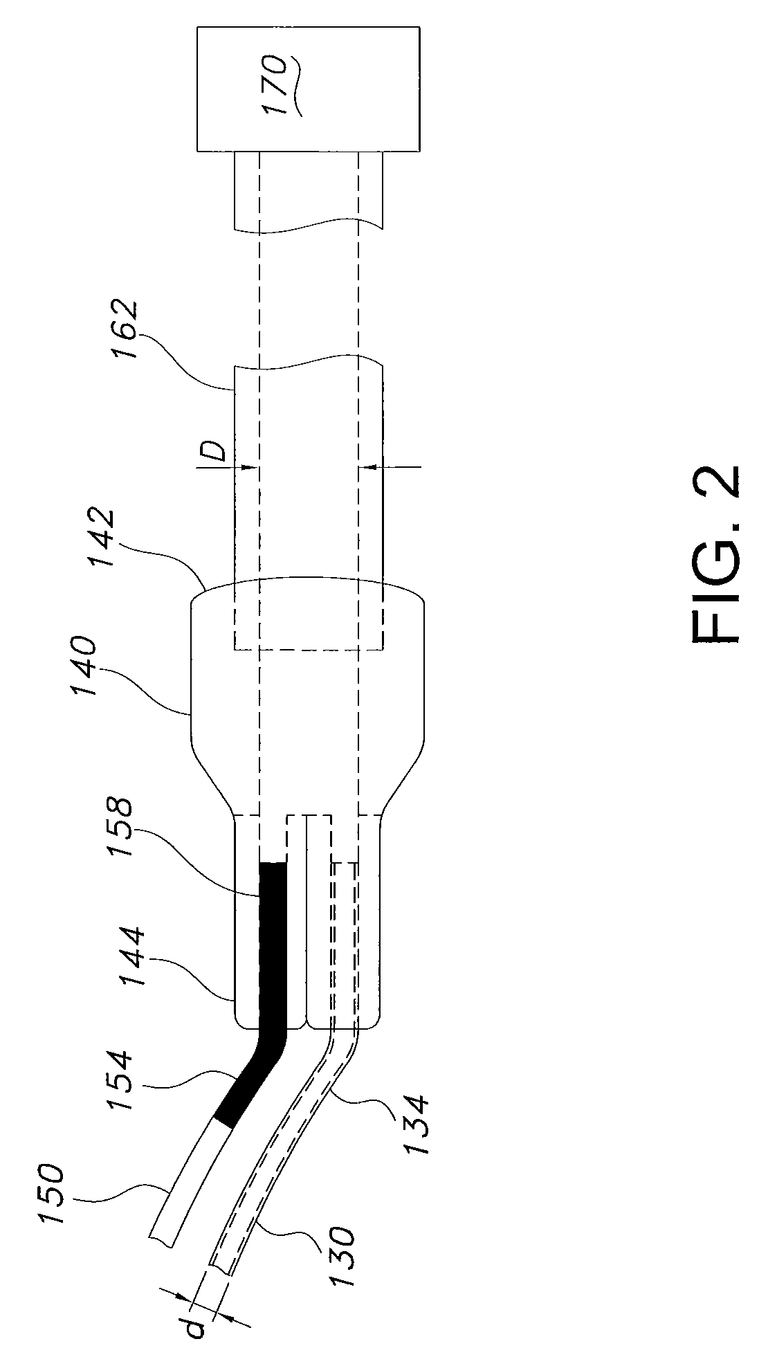
[0033]Referring to FIGS. 1-3 generally, a device in the form of a nasal cannula 100 is part of a conduit that is provided for delivering humidified breathing gas from a source of heated and humidified breathing gas to a patient. Nasal cannula 100 includes a nasal insertion member 110 that is used to deliver breathing gas to the pa...


PUM


Abstract

A system for delivering a humidified gas to a patient is disclosed. The system includes a supply tube having a first supply tube end and a second supply tube end. The supply tube has a first inner diameter. The system also includes an apparatus for delivering heated and humidified gas to the first end of the supply tube and a single lumen having a first lumen end and a second lumen end. The single lumen has a second inner diameter, smaller than the first diameter. The first lumen end is in fluid flow communication with the second supply tube end. The system also includes a nasal cannula in fluid flow communication with the second lumen end. A method of delivering heated and humidified gas to a patient is also disclosed.

Description

CROSS-REFERENCE TO RELATED APPLICATION[0001]The present application claims priority from U.S. Provisional Patent Application Ser. No. 60 / 859,222, filed on Nov. 15, 2006, which is incorporated by reference herein in its entirety.BACKGROUND OF THE INVENTION[0002]Delivery of oxygen and oxygen-enriched air to the respiratory tract of a patient can result in discomfort to the patient, especially when the air is delivered over an extended period of time. Delivery of air having relatively low absolute humidity can also result in respiratory irritation.[0003]When heating and humidifying a breathing gas for breathing through a nasal cannula, any cooling in the nasal cannula may lead to excessive condensation within the nasal cannula. When excessive condensation is present within the nasal cannula, drops of liquid water may subsequently be delivered to the patient's nose.SUMMARY OF THE INVENTION[0004]Briefly, the present invention provides a system for delivering a heated and humidified gas t...

Claims


Application Information

Patent Timeline
Patent Type & Authority Patents(United States)
IPC IPC(8): A62B7/00
CPCA61M16/0666A61M16/0683A61M16/08A61M16/0833A61M16/0688A61M16/1075A61M16/16A61M2205/3613A61M2205/3633A61M2205/42A61M16/0672
Inventor CORTEZ, JR., FELINO V.NILAND, WILLIAM F.BUYER, CARLMCGARRITY, GEORGE
Owner BRIDGE BANK NAT ASSOC
Learn More