Cooling circuits for a gas turbine blade

a technology of cooling circuit and gas turbine blade, which is applied in the direction of machines/engines, mechanical equipment, liquid fuel engines, etc., can solve the problems of limiting the lifetime of said parts and penalizing and achieve the effect of reducing the mean temperature of the blade and increasing the lifetime of the blad

Active Publication Date: 2005-02-03
SN DETUDE & DE CONSTR DE MOTEURS DAVIATION S N E C M A +2
View PDF10 Cites 58 Cited by
  • Summary
  • Abstract
  • Description
  • Claims
  • Application Information

AI Technical Summary

Benefits of technology

[0006] The present invention thus seeks to mitigate such drawbacks by proposing a gas turbine blade having cooling circuits that enable the mean temperature of the blade to be lowered and that avoid forming temperature gradients, in order to increase the lifetime of the blade.
[0008] Such a centrally-located first cooling circuit for the blade enables the mean temperature of the blade to be reduced while also reducing temperature gradients so as to increase the lifetime of the blade.
[0010] Such emission holes thus enable air films to be established in the bottom of the bathtub of the blade in order to protect it against hot gas.
[0012] Such bridges also serve to establish heat sink for transferring heat from the cavity wall that is in contact with the hot gas to the cooler wall of the cavity which is in contact with the central cavity, thus limiting the creation of temperature gradients in the blade.
[0013] Still advantageously, the pressure side cavity and the suction side cavity of the first cooling circuit have a large aspect ratio so as to increase internal heat transfer.

Problems solved by technology

These temperatures reach values that are well above those that can be withstood without damage by the various parts that come into contact with said gases, thereby limiting the lifetime of said parts.
Although the cooling appears to be satisfactory, such circuits are complex to make and it is found that the heat exchange produced by the flow of cooling air is not uniform, thereby leading to temperature gradients that penalize the lifetime of the blade.

Method used


Image

  • Cooling circuits for a gas turbine blade
  • Cooling circuits for a gas turbine blade
  • Cooling circuits for a gas turbine blade

Examples


Embodiment Construction

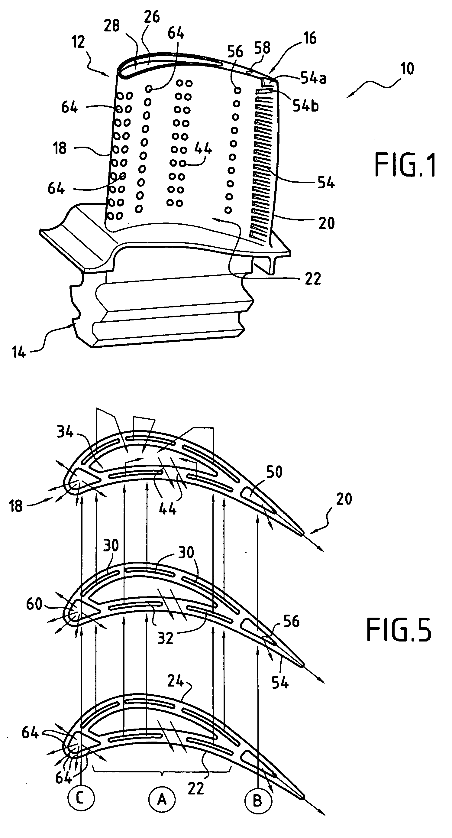
[0021]FIG. 1 shows a moving blade 10, e.g. made of metal, for a high-pressure turbine of a turbomachine. Naturally, the present invention can also be applied to other blades of the turbomachine, whether moving or stationary.

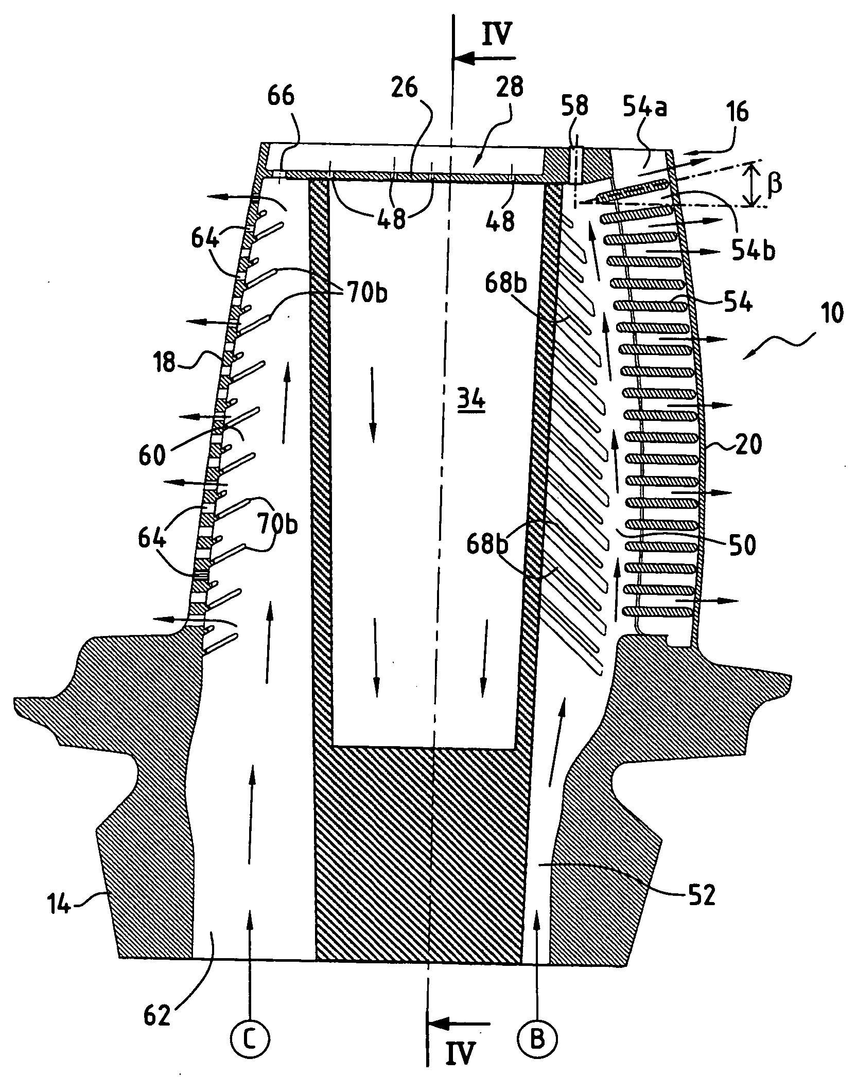
[0022] The blade 10 has an aerodynamic surface 12 which extends radially between a blade root 14 and a blade tip 16. The blade root 14 is for mounting on a disk of the rotor of the high pressure turbine.

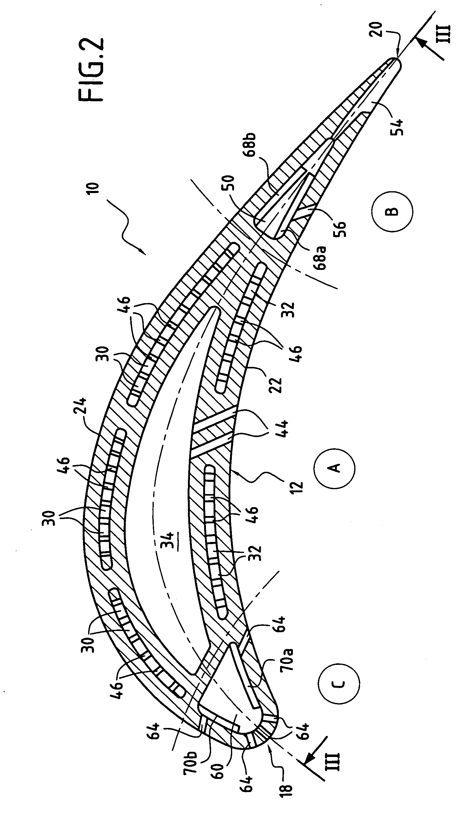
[0023] The aerodynamic surface 12 presents four distinct zones: a leading edge 18 placed facing the flow of hot gases coming from the combustion chamber of the turbomachine; a trailing edge 20 opposite from the leading edge 18; a pressure side face 22; and a suction side face 24, these side faces 22 and 24 interconnecting the leading edge 18 and the trailing edge 20.

[0024] At the blade tip 16, the aerodynamic surface 12 of the blade is closed by a transverse wall 26. In addition, the aerodynamic surface 12 extends radially slightly beyond said transverse wall 2...


PUM


Abstract

A gas turbine blade of a turbomachine includes in its central portion a centrally-located first cooling circuit at least a suction side cavity, at least a pressure side cavity, at least a central cavity extending between the suction side cavity and the pressure side cavity, a first air admission opening at a radially bottom end of the suction side cavity, a second air admission opening at a radially bottom end of the pressure side cavity, at least a first passage putting a radially top end of the suction side cavity into communication with a radially top end of the central cavity, at least a second passage putting a radially top end of the pressure side cavity into communication with the radially top end of the central cavity, and outlet orifices opening out both into the central cavity and into the pressure side face of the blade.

Description

BACKGROUND OF THE INVENTION [0001] The present invention relates to gas turbine blades for a turbomachine. More particularly, the invention relates to cooling circuits for such blades. [0002] It is known that the moving blades of a turbomachine gas turbine, and in particular of the high pressure turbine, are subjected to very high temperatures from the combustion gases when the engine is in operation. These temperatures reach values that are well above those that can be withstood without damage by the various parts that come into contact with said gases, thereby limiting the lifetime of said parts. [0003] It is also known that raising the temperature of the gas in the high pressure turbine increases turbomachine efficiency, i.e. the ratio of thrust from the engine over the weight of an airplane propelled by said turbomachine. Consequently, efforts are made to provide turbine blades that are capable of withstanding ever-higher temperatures. [0004] In order to solve this problem, it i...

Claims


Application Information

Patent Timeline
Patent Type & Authority Applications(United States)
IPC IPC(8): F01D5/18F01D5/20F02C7/12F02C7/18
CPCF01D5/187F01D5/20F05D2260/2212Y02T50/676F05D2260/202Y02T50/673Y02T50/60
Inventor BOTREL, ERWANENEAU, PATRICE
Owner SN DETUDE & DE CONSTR DE MOTEURS DAVIATION S N E C M A
Why Eureka
Try Eureka