Fluid visualisation and characterisation system and method; a transducer

a visualisation and characterisation system and fluid technology, applied in the field of fluid visualisation and characterisation systems and methods, can solve the problems of insufficient robustness and accuracy of systems/instrumentation and methodologies, inability to meet industrial requirements, and inability to readily sell uvp+pd systems, etc., to achieve the reduction of transducer sensitivity, reduce temperature gradients and vibrations, and improve the effect of accuracy

Active Publication Date: 2013-12-26
SP TECHNICAL RESEARCH INSTITUTE OF SWEDEN +1
View PDF7 Cites 55 Cited by
  • Summary
  • Abstract
  • Description
  • Claims
  • Application Information

AI Technical Summary

Benefits of technology

[0113]In the present invention, a circumference area, i.e. the outline area of the delay line material's cylindrical shape, may not be smooth. The outline area may be modified in such a way that undesired internal reflections inside the delay line material, which normally affect the performance of the delay line material and reduce the sensitivity of the transducer, are cancelled out. To this end, the outline area may be “non-smooth” e.g. terraced or stepped, or provided with bumps and crevasses at certain distances from the piezo element so that standing-wave phenomena (multiple reflections) causing blind spots are cancelled out. This in combination with the optimisation of the length and angle of the delay line may ensure that maximum acoustic energy is transmitted into the liquid of interest but also that the amplitude of the returning echo signals may not be attenuated as much as with existing del

Problems solved by technology

However, no commercial UVP+PD system is readily available on the market and systems used until now have been typically based on off-the-shelf transducers and electronics and are therefore more suited for simple flow characterisation with limited accuracy without meeting industrial requirements.
Also, conventional UVP+PD instruments typically used in research environments, systems/instrumentation and methodologies do not possess robustness and accuracy re

Method used


Image

  • Fluid visualisation and characterisation system and method; a transducer
  • Fluid visualisation and characterisation system and method; a transducer
  • Fluid visualisation and characterisation system and method; a transducer

Examples


Embodiment Construction

[0134]In the following description, for purposes of explanation, numerous specific details are set forth in order to provide a thorough understanding of an embodiment of the present disclosure. It will be evident, however, to one skilled in the art that the present invention may be practiced without these specific details.

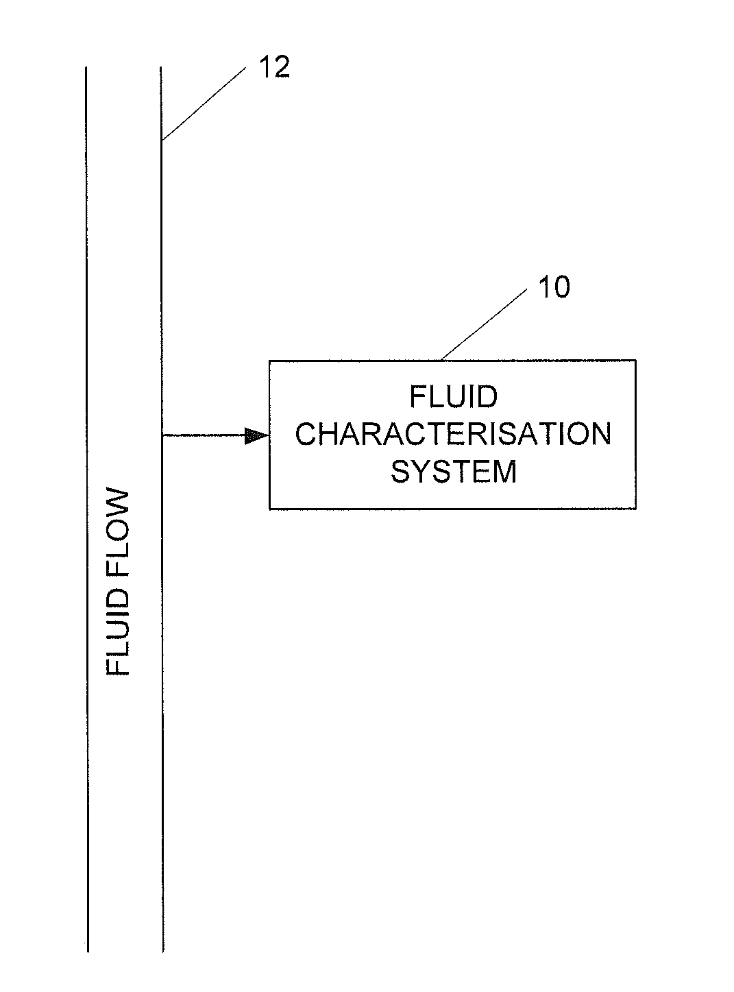
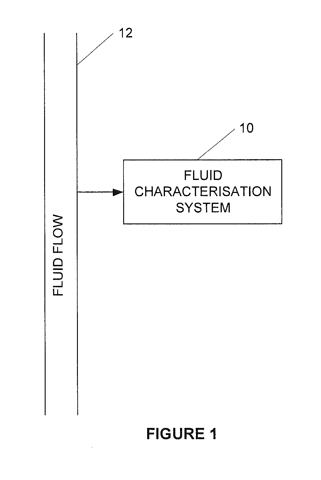
[0135]Referring to FIG. 1 of the drawings a fluid visualization and characterisation system in accordance with the invention is generally indicated by reference numeral 10. At least a section of the system 10, for example, a measuring section thereof, is typically integrated with or connectable to a fluid network comprising means defining fluid flow paths for fluids flowing in the fluid network. The means are typically pipes 12 in a pipe network. Advantageously, the pipes 12 may form part of an industrial processing pipe network or circuit of the fluid network. The means could instead be other conduits capable of conveying fluids.

[0136]The system 10 also comprises ...


PUM


Abstract

A fluid visualization and characterisation system includes a measuring section with a housing defining a fluid flow path for fluid flow. The measuring section includes one or more transducers to emit ultrasonic signals into the fluid flow, and at least one receiver to receive reflections of the ultrasonic signal from reflectors in the fluid flow. The system includes a memory for storing data and a processor operatively connected to the memory. The processor comprises several modules. A velocity estimating module is configured to apply one or more velocity estimation algorithms to received reflections of the ultrasonic signal, or data indicative thereof, to determine a velocity profile of the fluid flow. A deconvolution module is configured to apply a deconvolution algorithm at least to the determined velocity profile to determine a true velocity profile of the fluid flow. A fluid visualization and characterisation module is configured to determine characteristics of the fluid and/or fluid flow in by using the determined velocity profile and/or the true velocity profile.

Description

CROSS-REFERENCE TO RELATED APPLICATIONS[0001]This application is a by-pass continuation application of International Application No. PCT / IB2012 / 053244, which has an international filing date of 27 Jun. 2012, and which claims priority to South African Patent Application No. 2011 / 05745, filed 4 Aug. 2011.BACKGROUND OF THE INVENTION[0002]1. Field of the Invention[0003]This invention relates to a method and system for visualizing and characterising fluids flowing in a means defining a fluid flow path.[0004]2. Related Art[0005]Pulsed Ultrasound Velocimetry (PUV) is a technique for measuring an instantaneous velocity profile in liquid flow along a pulsed ultrasonic beam axis. The instantaneous velocity profile is obtained by detecting the relative time lags of backscattered ultrasound echoes from moving particles between successive pulse emissions. As shown in the article by D. W. Baker, ‘Pulsed Ultrasonic Doppler Blood-Flow Sensing’, IEEE Transactions on Sonics and Ultrasonics, vol. SU-1...

Claims


Application Information

Patent Timeline
IPC IPC(8): G01F1/66
CPCG01F1/66G01F1/34G01F1/662G01F1/663G01F1/668G01F1/704G01F15/00G01F15/024G01N11/08
Inventor WIKLUND, JOHANHALDENWANG, RAINERKOTZE, REINHARDT
Owner SP TECHNICAL RESEARCH INSTITUTE OF SWEDEN
Why Eureka
Try Eureka