Air diffuser apparatus

a technology of air diffuser and apparatus, which is applied in the field of air diffuser, can solve the problems of non-satisfactory and/or problematic configuration, and none of the above-identified apparatuses appear to be configured to effectively reduce and/or eliminate temperature non-uniformity, etc., and achieves the effect of reducing the draft during operation, facilitating substantially even air distribution, and reducing the temperature gradient in the associated room

Active Publication Date: 2010-01-12
PEERBOLT MORRIS
View PDF22 Cites 61 Cited by
  • Summary
  • Abstract
  • Description
  • Claims
  • Application Information

AI Technical Summary

Benefits of technology

[0027]In still another preferred embodiment of the present invention, the air diffuser facilitates substantially even distribution of air throughout an associated room, substantially reduces drafts during operation of an associated air distribution system, and / or substantially reduces a temperature gradient in an associated room.

Problems solved by technology

While the above-identified patents do appear to provide air diffuser apparatuses, their configurations remain non-desirous and / or problematic inasmuch as, among other things, none of the above-identified apparatuses appear to be configured to effectively reduce and / or eliminate temperature non-uniformity, such as, for example, hot spots, cold spots, drafts, etcetera—among other things.

Method used


Image

  • Air diffuser apparatus
  • Air diffuser apparatus
  • Air diffuser apparatus

Examples


Embodiment Construction

[0036]While this invention is susceptible of embodiment in many different forms, there is shown in the drawings and described herein in detail several specific embodiments with the understanding that the present disclosure is to be considered as an exemplification of the principles of the invention and is not intended to limit the invention to the embodiments illustrated.

[0037]It will be understood that like or analogous elements and / or components, referred to herein, may be identified throughout the drawings with like reference characters.

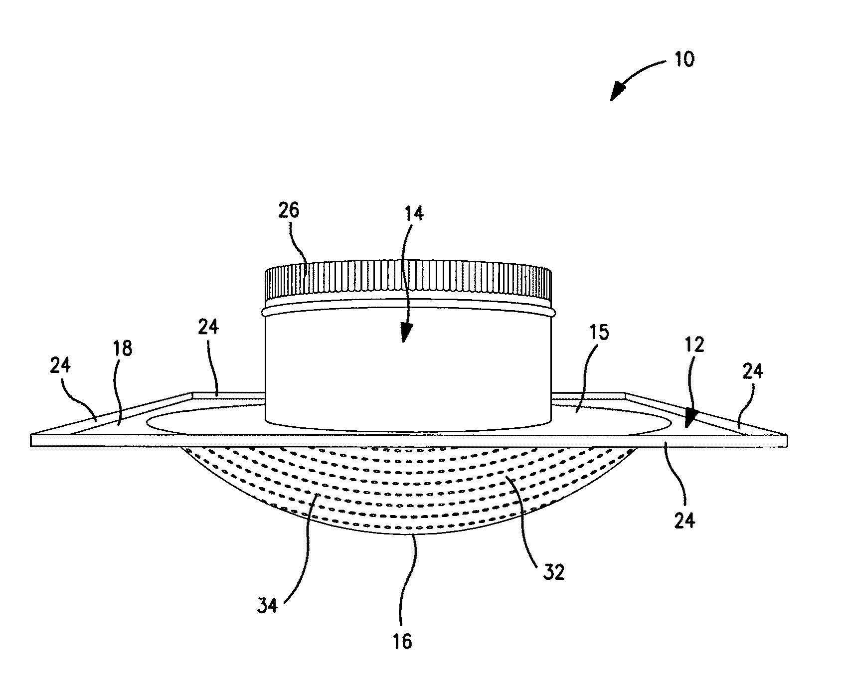
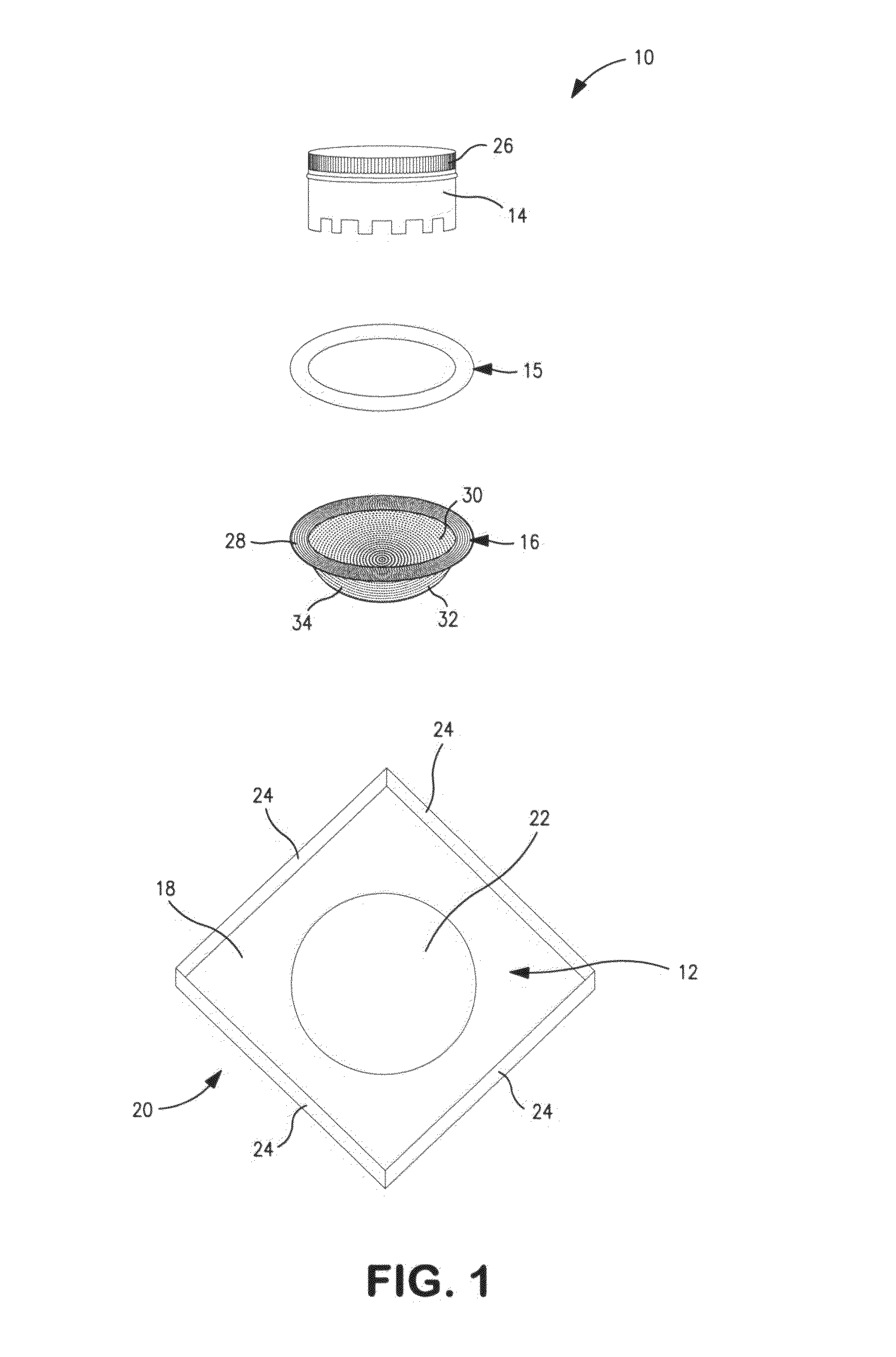
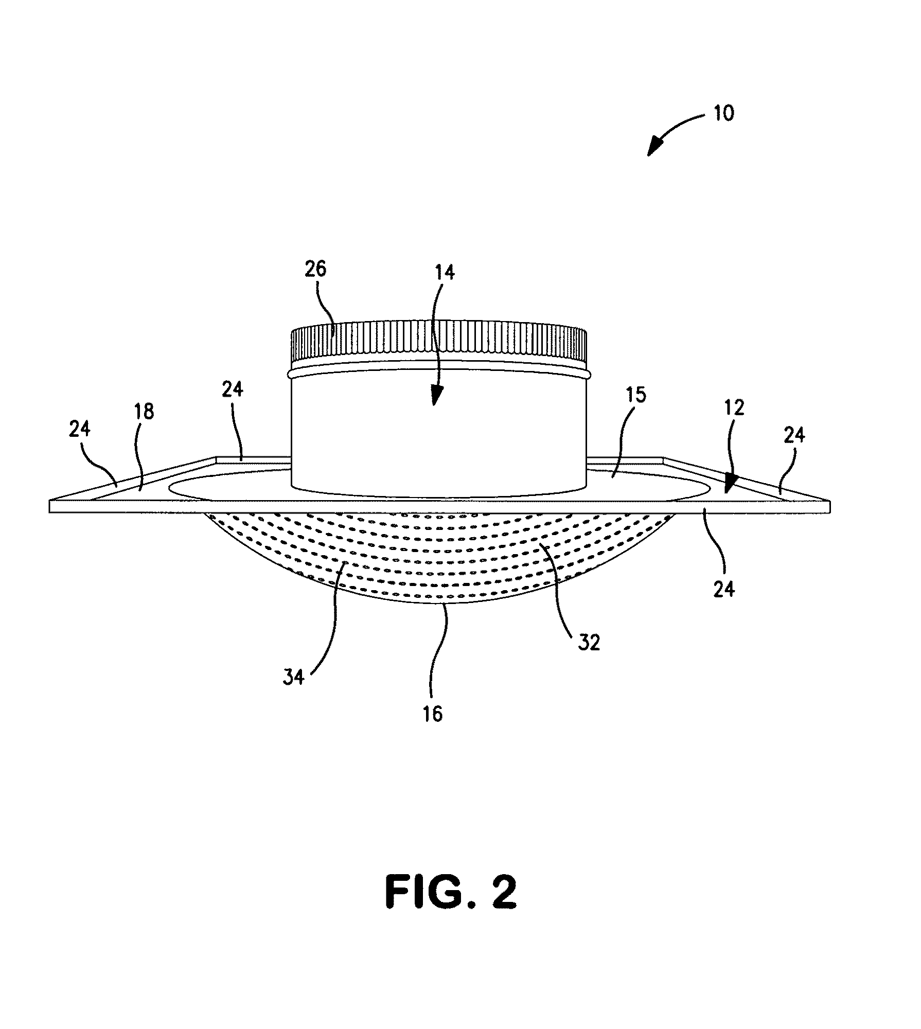
[0038]Referring now to the collective drawings (i.e. FIGS. 1-4), and to FIG. 1 in particular, an exploded perspective view of a first embodiment of air diffuser apparatus 10 is shown which generally comprises frame member 12, attachment member 14, and diffusing member 16. It will be understood that air diffuser apparatus 10 may be fabricated from a unitary member or a plurality of pieces. It will be further understood that FIG. 1 is merely a repre...


PUM


Abstract

An air diffuser for distributing air into a room from a supply duct of an air distribution system having: a frame member, wherein the frame member includes an inner surface, and an outer surface; an attachment member, wherein the attachment member is associated with the frame member, and further wherein the attachment member is configured for associating the air diffuser with a supply duct; and a diffusing member, wherein the diffusing member comprises a substantially hemispherical dome having an inner surface, an outer surface, and a plurality of apertures, and wherein the substantially hemispherical dome emanates away from the outer surface of the frame member.

Description

CROSS-REFERENCE TO RELATED APPLICATION(S)[0001]Not ApplicableBACKGROUND OF THE INVENTION[0002]1. Field of the Invention[0003]The present invention relates in general to air diffusers and, more particularly, to air diffusers which are adapted for mounting in a wall or ceiling of a room for distributing air into the room from an air distribution system, such as a heating, ventilation, and air-conditioning (HVAC) system.[0004]2. Background Art[0005]Air diffusers have been known in the art for years, and are the subject of numerous patents, including: U.S. Pat. No. D325,434 entitled “Air Diffuser,” U.S. Pat. No. D521,631 entitled “Air Diffuser,” U.S. Pat. No. 3,403,614 entitled “Environmental Enclosure With Ceiling Air Plenum,” U.S. Pat. No. 3,559,560 entitled “Ceiling Boxes For Distributing Air,” U.S. Pat. No. 4,020,752 entitled “Air Diffuser With Modular Core,” U.S. Pat. No. 5,807,171 entitled “Air Diffuser Apparatus,” U.S. Pat. No. 6,135,878 entitled “Modular Core Air Diffusers,” and...

Claims


Application Information

Patent Timeline
Patent Type & Authority Patents(United States)
IPC IPC(8): F24F13/06F24F13/08
CPCF24F13/06
Inventor PEERBOLT, MORRIS
Owner PEERBOLT MORRIS
Why Eureka
Try Eureka