

Method and system for preparing sponge iron by using gas-based shaft furnace
A gas-based shaft furnace and sponge iron technology, applied in the field of metallurgy, can solve the problems of low carbon monoxide content, difficulty in reaching the center of the shaft furnace for reducing gas, and large-scale reducing gas heating equipment.
- Summary
- Abstract
- Description
- Claims
- Application Information
AI Technical Summary
Problems solved by technology
Method used
Image

Examples
Embodiment 1
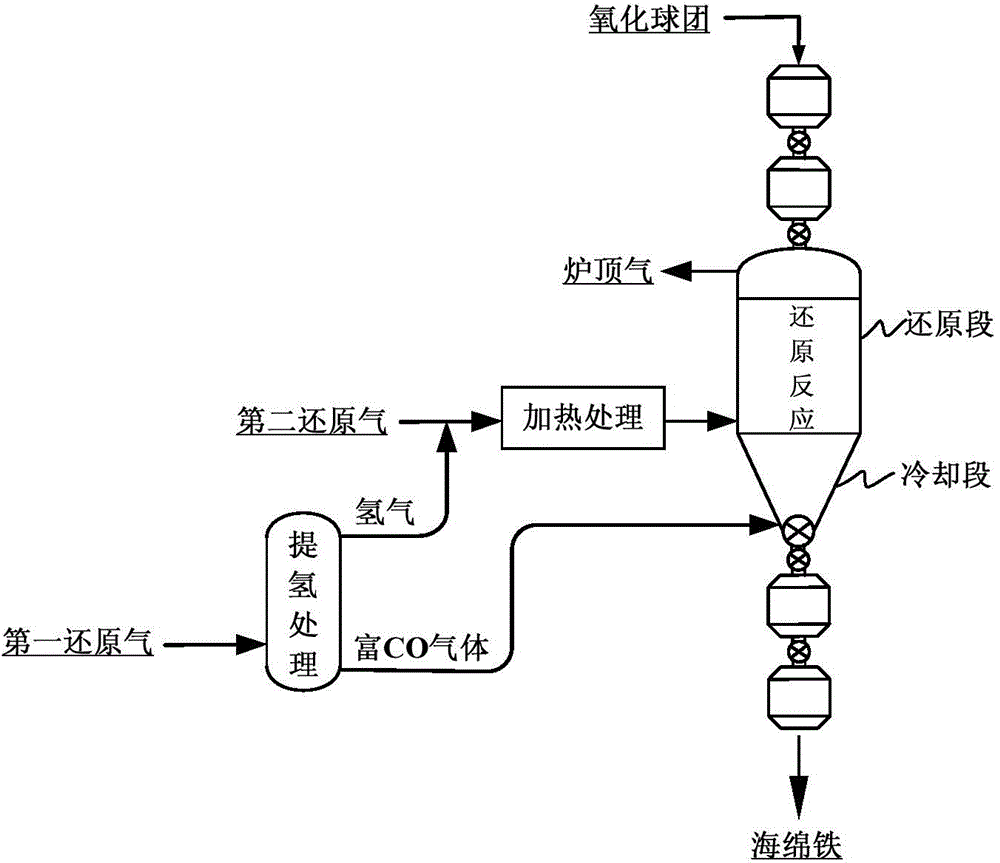
[0093] Such as figure 2 and Figure 7 As shown, the fresh reducing gas is divided into two parts, one part passes through the gas hydrogen extraction device, and this part of the gas is divided into hydrogen and carbon monoxide-rich gas, and the hydrogen and the other part of the fresh reducing gas are passed into the gas heating furnace for heating to 900-1000 degrees Celsius, and then enter the shaft furnace reduction section from the surrounding pipe at the bottom of the shaft furnace reduction section to carry out reduction reaction with the oxidized pellets entering from the upper part of the shaft furnace. The carbon monoxide-rich gas passes into the bottom of the cooling section of the shaft furnace to exchange heat with the hot sponge iron, and cools the sponge iron to below 50°C in the cooling section of the shaft furnace, while the carburizing reaction consumes part of the carbon monoxide. This part of the carbon monoxide-rich gas is heated to 850-900 degrees Celsi...
Embodiment 2
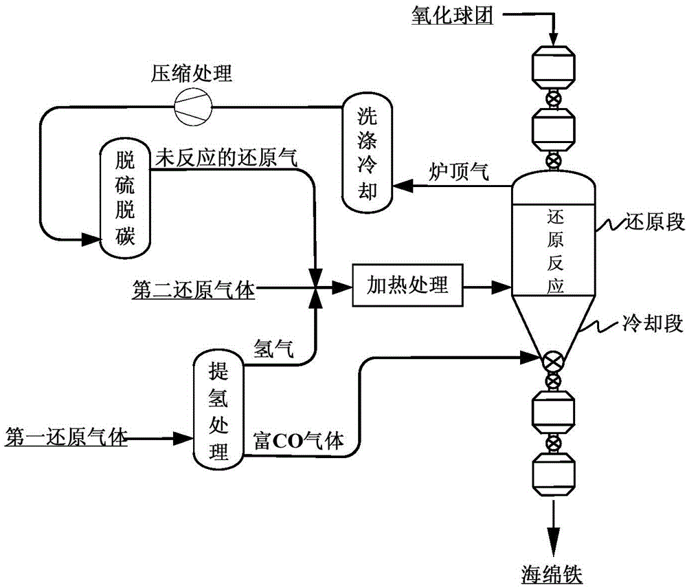
[0096] Such as image 3 and Figure 8 As shown, the fresh reducing gas is passed into the gas heating furnace for heating to 900-1000 degrees Celsius, and then enters the shaft furnace reduction section from the surrounding pipe at the bottom of the shaft furnace reduction section to perform reduction reaction with the oxidized pellets entering from the upper part of the shaft furnace. The sponge iron is obtained and the top gas is produced, the sponge iron enters the cooling section, and the generated top gas is discharged from the top gas outlet of the shaft furnace.
[0097] The exhausted furnace top gas is washed and cooled, compressed, desulfurized and decarburized to obtain unreacted reducing gas, and the unreacted reducing gas is subjected to hydrogen extraction treatment to obtain hydrogen and carbon monoxide-rich gas respectively. The fresh reducing gas is fed into the gas heating furnace together for heating. The carbon monoxide-rich gas is passed into the bottom o...
Embodiment 3
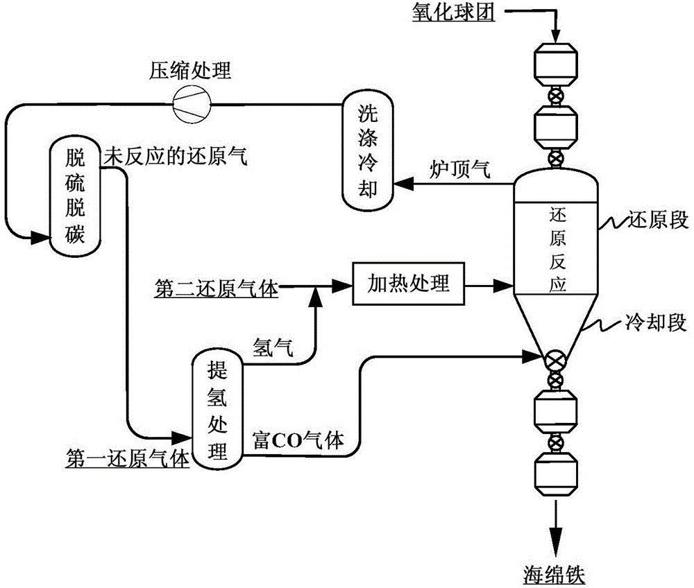
[0099] Such as Figure 5 and Figure 9 As shown, the fresh reducing gas is divided into two parts, one part passes through the gas hydrogen extraction device, and this part of the gas is divided into hydrogen and carbon monoxide-rich gas, and the hydrogen and the other part of the fresh reducing gas are passed into the gas heating furnace for heating to 900-1000 degrees Celsius, and then enter the shaft furnace reduction section from the surrounding pipe at the bottom of the shaft furnace reduction section to carry out reduction reaction with the oxidized pellets entering from the upper part of the shaft furnace. The carbon monoxide-rich gas passes into the bottom of the cooling section of the shaft furnace to exchange heat with the hot sponge iron, and cools the sponge iron to below 50°C in the cooling section of the shaft furnace, while the carburizing reaction consumes part of the carbon monoxide. This part of the carbon monoxide-rich gas is heated to 850-900 degrees Celsi...
PUM
 Abstract
Description
Claims
Application Information