Method and apparatus for monitoring intra ocular and intra cranial pressure

a technology of intra ocular and intra cranial pressure, which is applied in the direction of diagnostic recording/measuring, ultrasonic/sonic/infrasonic image/data processing, applications, etc., can solve the problems of not having a feasible clinical device, medical condition that can be life-threatening, and increased pressure in the brain, so as to achieve rapid and sensitive readings, timely identification and treatment of elevated icp

Active Publication Date: 2012-05-08
VIRGINIA COMMONWEALTH UNIV
View PDF9 Cites 11 Cited by
  • Summary
  • Abstract
  • Description
  • Claims
  • Application Information

AI Technical Summary

Benefits of technology

[0011]A further object of the invention is to enable timely identification and treatment of elevated ICP.

Problems solved by technology

Pressure increase in the brain, which is contained within the skull, is a serious medical condition that can be life threatening.
In pathological circumstances such as stroke or head injury, elevated ICP poses a clinical problem that must be carefully managed to prevent severe brain damage or even the death of the patient.
Ear monitoring of changes in cerebral spinal fluid (CSF) pressure have been attempted but have not resulted in a feasible clinical device.
Direct measures of skull vibration by using ultrasonic probes have also been attempted, but with limited success because it is technically complicated, and is not a promising clinical alternative.
This technique has produced conflicting results and at best provides only a rough estimate of ICP.
However, this measure cannot be equated with ICP.
There have been previous attempts by other researchers to acoustically measure ICP in animals, but although they have proven the validity of the concept, they have not been practical for portable use in humans.
However, although their method did not require surgery within the skull cavity, it did require implantation of screws in the skull, making it impractical for a portable system.

Method used


Image

  • Method and apparatus for monitoring intra ocular and intra cranial pressure
  • Method and apparatus for monitoring intra ocular and intra cranial pressure
  • Method and apparatus for monitoring intra ocular and intra cranial pressure

Examples


Embodiment Construction

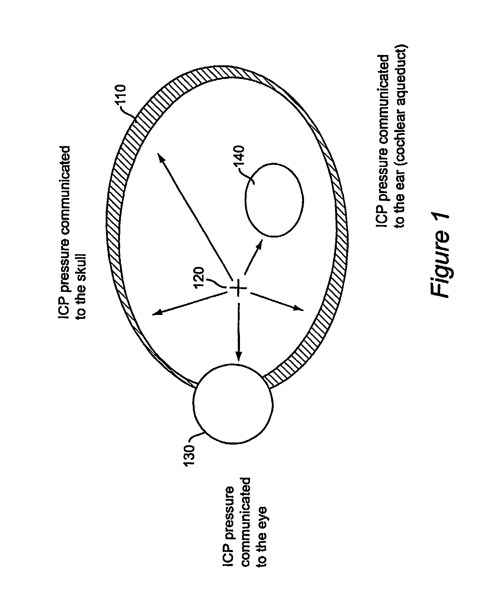
[0025]Referring now to the drawings, and more particularly to FIG. 1, there is shown a conceptual schematic of a skull 110, within which and upon which the brain's cerebral spinal fluid (CSF) exerts pressure 120. This pressure 120 is not only communicated to the skull 110 but is also communicated to the eye 130 and the ear 140. The brain and the skull are coupled resonant systems that will respond in a predictable fashion to pressure increases. Changes in acoustic damping are correlated with changes in cerebral spinal fluid (CSF) or intra cranial pressure (ICP).

[0026]Any physical or biological system that has an acoustic resonance will be characterize by a narrow range of frequencies which will cause the system to oscillate, i.e. force resonance. A fine wine glass can be forced into vibration and it will oscillate with the greatest amplitude at its resonance frequency. Sometime the amplitude is so great the glass shatters. However, natural resonance can be reduced in amplitude by da...


PUM


Abstract

A method and apparatus for measuring acoustic energy applied to the head to detect increases in intracranial pressure. Acoustic eye patches are applied to a patient's eye or eyelid, and an ultrasonic sweep generator applies an acoustic signal across the patient's skull, the signal being swept across a predetermined range. The eye patches have piezoelectric film sensors for measuring the acoustic signal. In one embodiment the predetermined range is in the ultrasonic band and an analyzer determines from the output of the sensors a resonant frequency and a damping of acoustic amplitude at said resonant frequency, there being a correlation between said damping and intra cranial pressure. In another embodiment the predetermined range includes a range less than 20 kHz and the analyzer determines retinal artery pulsations, with pressure being applied to the eye until the pulsations disappear, such pressure being a measure of intra cranial pressure.

Description

BACKGROUND OF THE INVENTION[0001]1. Field of the Invention[0002]The present invention generally relates to non-invasive techniques for diagnosis of medical conditions, and in particular to use of such techniques for monitoring pressure within the cranium.[0003]2. Background Description[0004]Pressure increase in the brain, which is contained within the skull, is a serious medical condition that can be life threatening. The brain is surrounded by cerebrospinal fluid; the pressure of the fluid, known as intra cranial pressure (ICP), is carefully controlled by homeostatic mechanisms in the body. In pathological circumstances such as stroke or head injury, elevated ICP poses a clinical problem that must be carefully managed to prevent severe brain damage or even the death of the patient. Intra cranial pressure changes can be detected non invasively using acoustic stimulation and analysis. The brain and the skull are coupled resonant systems that will respond in a predictable fashion to p...

Claims


Application Information

Patent Timeline
Patent Type & Authority Patents(United States)
IPC IPC(8): A61B5/00A61BA61B3/16A61B5/03A61B8/08
CPCA61B5/031A61B5/6814A61B8/0808A61B8/4227A61B5/6821
Inventor LENHARDT, MARTIN MWARD, KEVIN
Owner VIRGINIA COMMONWEALTH UNIV
Why Eureka
Try Eureka