
Wire electrode type ionizer

a wire electrode and ionizer technology, applied in the direction of electrostatic charges, electrical equipment, etc., can solve the problems of disturbing the ion balance of the generated ions, affecting the performance of the electrode for a long time, and the top end of the electrode is likely to be deteriorated, so as to prolong the maintenance interval, improve the ionic balance, and reduce the consumption of the wire electrode by ozone

Active Publication Date: 2012-05-08
SMC CORP
View PDF10 Cites 19 Cited by
  • Summary
  • Abstract
  • Description
  • Claims
  • Application Information

AI Technical Summary

Benefits of technology

[0005]The present invention provides a wire electrode type ionizer capable of keeping a balance between positive and negative ions in a good condition by improving the electrode structure to increase the ion generation amount while suppressing such problem as facilitation of ozone generation as a result of raising the voltage applied to the electrode.
[0011]In the present invention, high voltages to be applied to the positive and the negative wire electrodes may be set to be within a range having a short charging time at a critical applied voltage or lower in which an ozone generation amount is sharply increased by raising an applied voltage. This makes it possible to suppress consumption of the wire electrode by ozone, thus prolonging the maintenance interval.
[0012]In the above-structured wire electrode type ionizer, the high voltage generator unit applies pulse DC type high voltages, that is, positive pulse high voltage and the negative pulse high voltage are applied alternately to the positive and negative wire electrodes. When the DC type high voltages, that is, the positive and the negative high voltages are applied to the positive and negative wire electrodes, the ion generation region is formed around both wire electrodes so as to be discharged. If each diameter of the wire electrodes is the same, the negative ion is generated more than the positive ion. So the diameter of the electrode which receives application of the negative high voltage is made larger than that of the electrode which receives application of the positive high voltage to adjust the ion generation amount, thus improving the ionic balance.
[0013]The electrode structure is improved by using the wire electrode to increase the ion generation amount while keeping the ionic balance between the positive and the negative ions without increasing the voltage applied to the electrode to facilitate the ozone generation. The present invention also suppresses the ozone generation amount, and prolongs the maintenance interval of the wire electrode.

Problems solved by technology

The focusing of the electric field to the top end of the needle electrode is so intense that the top end of the electrode is likely to be deteriorated, thus degrading the performance for a long-term use.
When employing the aforementioned ionizer for alternately applying the positive and the negative voltages at the same level to the single wire electrode, generation amounts of the positive and the negative ions become different, thus disturbing the balance of the generated ions.
However, this may cause the problem resulting from the intense electric field around the electrode owing to the high voltage.

Method used


Image

  • Wire electrode type ionizer
  • Wire electrode type ionizer
  • Wire electrode type ionizer

Examples


Embodiment Construction

[0022]An embodiment of the present invention will be described referring to the drawings.

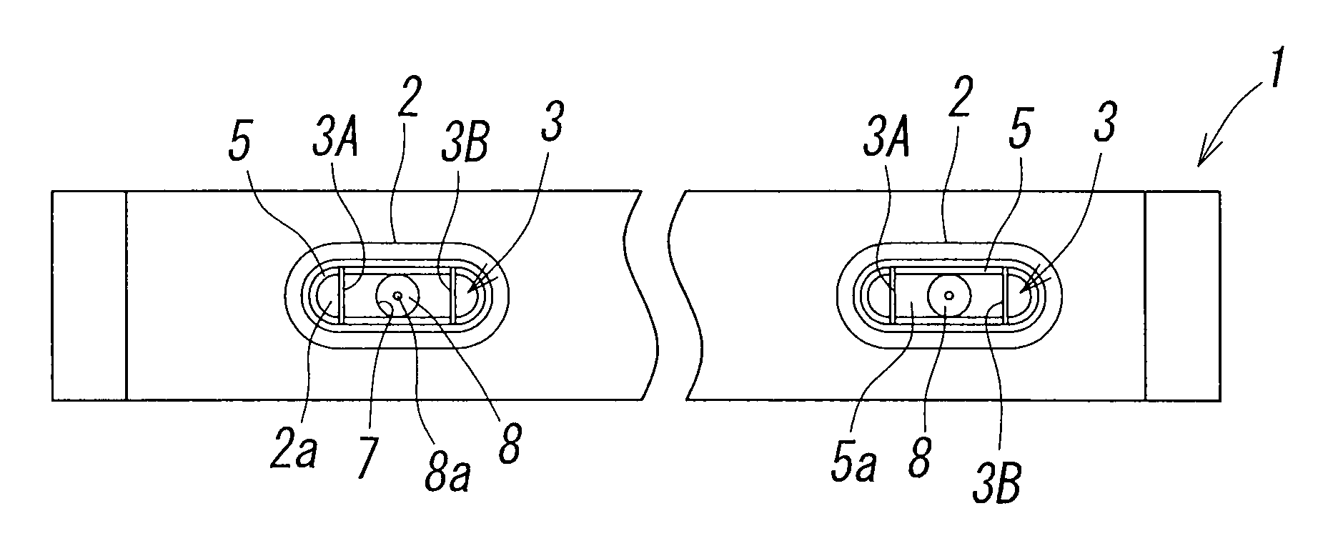
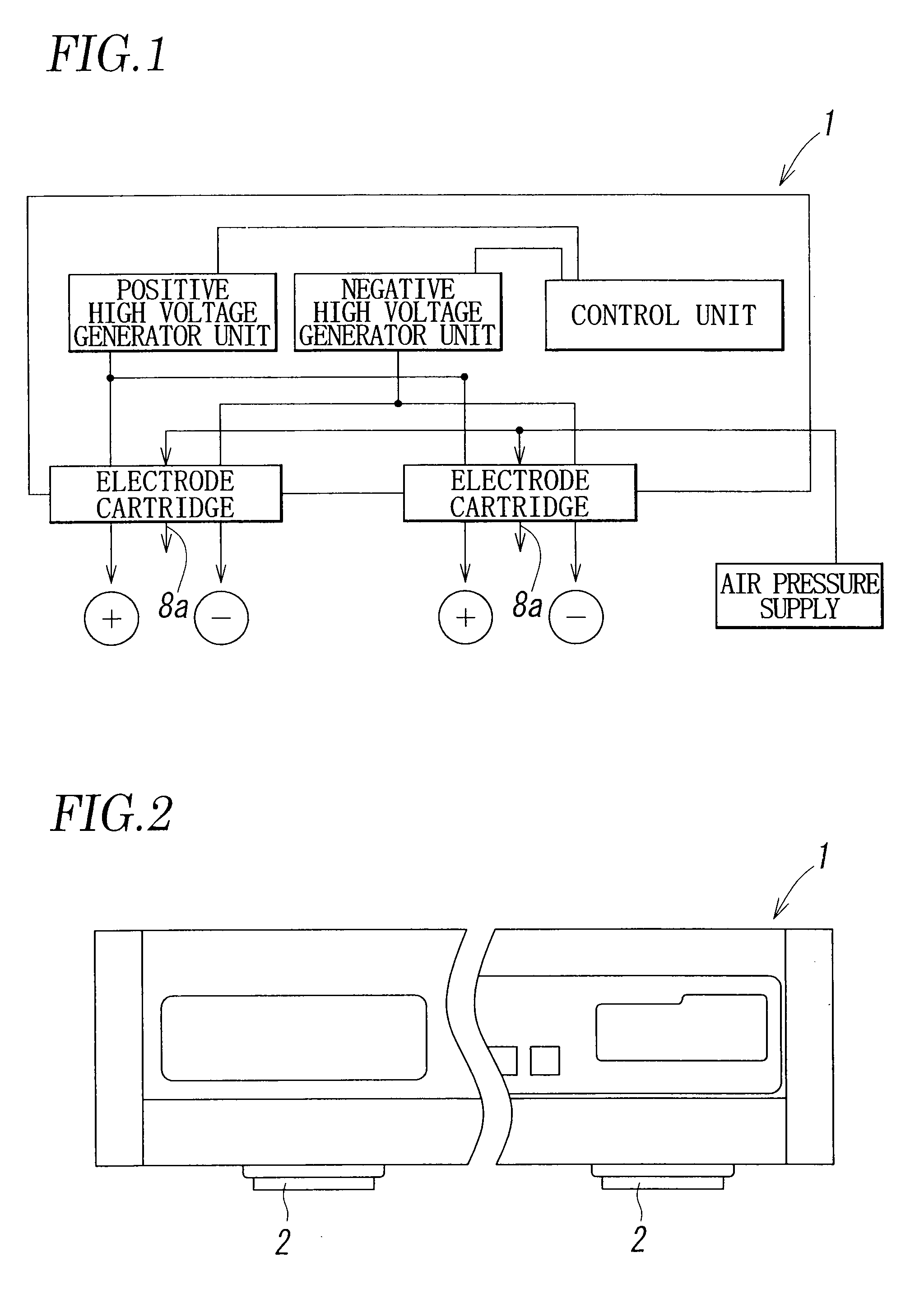
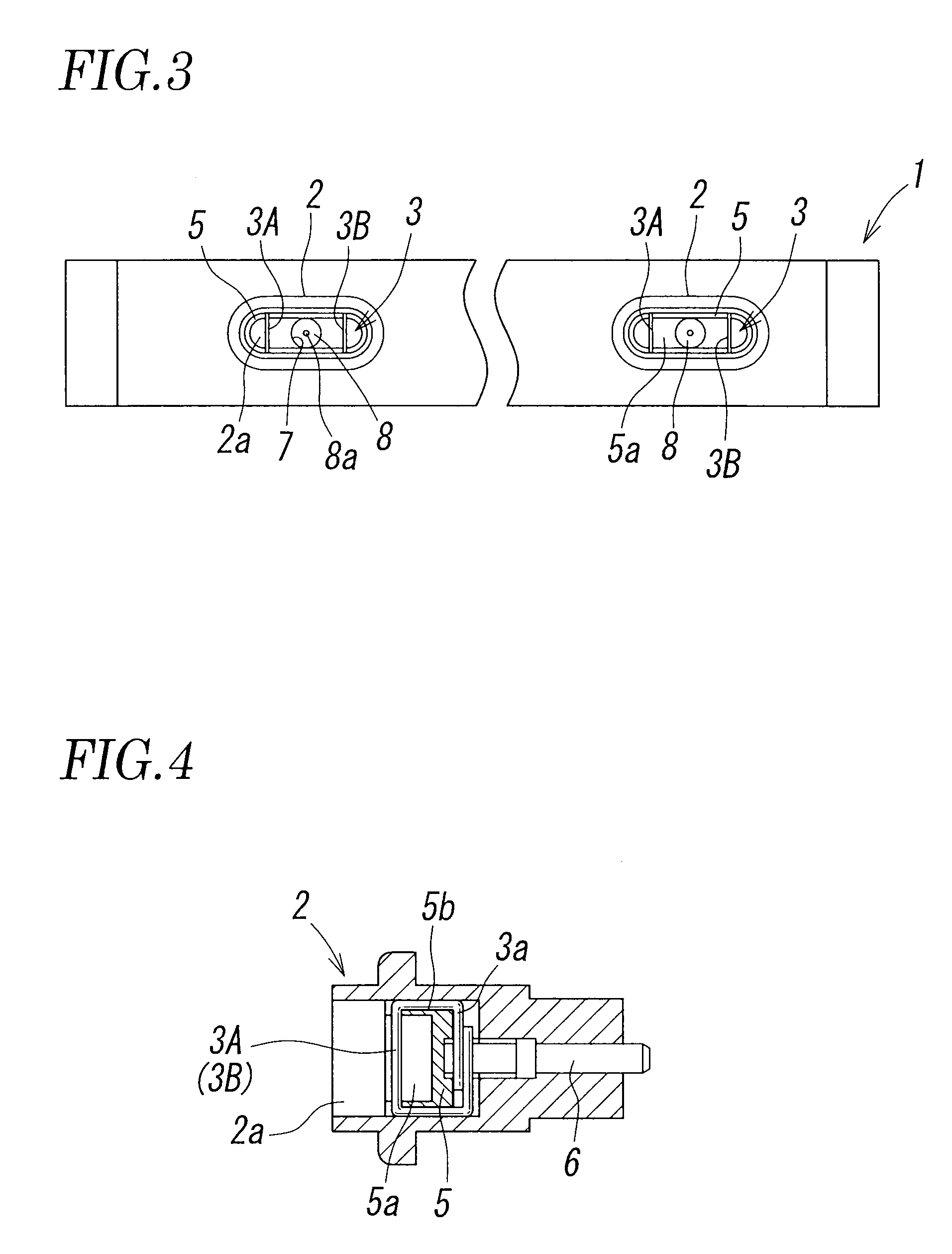
[0023]FIG. 1 is a block diagram schematically showing an entire structure of a wire electrode type ionizer according to the present invention. FIGS. 2 to 4 show a structures of essential portions of the embodiment.

[0024]The wire electrode type ionizer of DC type is provided with positive and negative high voltage generator units each having the voltage controlled by a control unit, and a discharge electrode 3 formed of positive and negative wire electrodes 3A and 3B in a housing 1. Positive and negative high voltages are applied from the high voltage generator units to the wire electrodes 3A and 3B so as to generate corona discharge, thus allowing the wire electrodes 3A and 3B to generate positive and negative ions.

[0025]Specifically, the ionizer has a horizontally thin and long hollow housing 1 as shown in FIGS. 2 and 3. A plurality of electrode cartridges 2 each having the discharge electrode ...


PUM


Abstract

An ionizer includes positive and negative wire electrodes each formed of a conductive wire with a circular cross section. The wire electrodes are arranged in parallel with each other, each having circumferential surfaces serving as a discharge surface on which a corona discharge occurs upon application of positive and negative high voltages for discharging positive and negative ions.

Description

TECHNICAL FIELD[0001]The present invention relates to a wire electrode type ionizer for neutralizing various types of electrostatically charged works.BACKGROUND ART[0002]A generally employed ionizer applies high voltage to a needle electrode for generating ions by focusing the field to a top end of the needle electrode. The focusing of the electric field to the top end of the needle electrode is so intense that the top end of the electrode is likely to be deteriorated, thus degrading the performance for a long-term use.[0003]As the needle electrode has a narrow ion generation region, the resultant ion generation amount is small. The ion generation amount may be increased by raising the voltage. However, the electric field at the top end of the needle electrode becomes so intense that generation of ozone with strong oxidative power is facilitated.[0004]Patent Document, Japanese Unexamined Patent Application Publication No. 10-189282, discloses the ionizer for generating ions on a cir...

Claims


Application Information

Patent Timeline
Patent Type & Authority Patents(United States)
IPC IPC(8): H01T23/00
CPCH01T23/00H05F3/04
Inventor YASUOKA, KOICHIMIYATA, YOUHEIFUJIWARA, NOBUHIROSUZUKI, SATOSHISATO, TOSHIO
Owner SMC CORP
Learn More