Recording device

a recording device and a technology for recording media, applied in printing, other printing apparatus, etc., can solve the problem that the floating of the recording medium from the transport belt cannot be sufficiently suppressed

Active Publication Date: 2012-05-15
SEIKO EPSON CORP
View PDF11 Cites 2 Cited by
  • Summary
  • Abstract
  • Description
  • Claims
  • Application Information

AI Technical Summary

Benefits of technology

[0006]According to an aspect of the invention, there is provided a recording device including: a first suction unit which has a support member for supporting a recording medium and a plurality of suction holes provided in the support member to support the recording medium under control that a second suction force of the suction holes not covered by the recording medium is restricted to be smaller than a first suction force of the suction holes covered by the recording medium; a recording head which performs recording on the recording medium supported by the first suction unit; and a second suction unit which has a support member for supporting a recording medium and a plurality of suction holes provided in the support member and is disposed near the first suction unit in a transport direction of the recording medium and in which a third suction force of the suction holes not covered by the recording medium is set to be larger than the second suction force. Accordingly, an effect of airflow on a flight state of ink droplets can be suppressed and floating of a recording medium from the support member can be sufficiently suppressed.
[0008]In the recording device, each of the first suction unit and the second suction unit may have a plurality of communication channels communicating a suction force generating section which generates a suction force for sucking air with the suction holes, and a suction force adjusting section provided to correspond to the suction holes and restricting the first suction force to be smaller than the second suction force, the communication channel may have: a hole-side channel section which is closer to the suction hole than the suction force adjusting section; and a suction-side channel section which is closer to the suction force generating section than the suction force adjusting section, the suction force adjusting section may have: a diaphragm which is arranged between the hole-side channel section and the suction-side channel section and is displaced toward the hole-side channel section or the suction-side channel section by a differential pressure between the hole-side channel section and the suction-side channel section; an open-close communication hole which is formed in the diaphragm, is opened and closed by the displacement of the diaphragm and communicates the hole-side channel section with the suction-side channel section in an opened state; and an open communication hole which is formed in the diaphragm, is opened regardless of the position of the diaphragm and communicates the hole-side channel section with the suction-side channel section, and a hole diameter of the open communication hole disposed in the recording area may be smaller than a hole diameter of the open communication hole disposed on the upstream side of the recording area in the transport direction. Accordingly, a channel cross-sectional area of some of the communication channels communicating with the suction holes opened in the recording area can be made narrower than that on the upstream side or the downstream side of the recording area in the transport direction. As a result, a recording medium on the upstream side or the downstream side in the transport direction can be sufficiently sucked onto the support member to sufficiently suppress floating of the recording medium from the support member, and airflow generated in the recording area can be weakened to suppress an effect of the airflow on a flight state of ink droplets.
[0011]According to another aspect of the invention, there is provided a recording device including: a recording head which performs recording by ejecting ink on a recording medium; a transport member which has a plurality through holes formed therein to transport the recording medium to a recording area of the recording head; a suction unit which has a suction force generating section which generates a suction force for sucking air and a plurality of communication channels which communicate the suction force generating section with the through holes, and sucks the recording medium onto the transport member by generating a suction force in the through holes; and a suction force adjusting section which is provided to correspond to at least the through holes positioned in the recording area and restricts a suction force of the through holes opened to be smaller than a suction force of the through holes blocked by the recording medium, and by the suction force adjusting section, the suction force generated in the opened through holes positioned in the recording area can be made weaker than the suction force generated in the opened through holes positioned on the upstream side or the downstream side of the recording area in the transport direction. Accordingly, airflow generated in the recording area can be weakened to suppress an effect of the airflow on a flight state of ink droplets, and a suction force between a recording medium and the transport member on the upstream side or the downstream side of the recording area in the transport direction can be sufficiently ensured to sufficiently suppress floating of the recording medium at the stage where suction is started or after recording from the transport member.
[0012]In the recording device, when the through holes are blocked by a recording medium, the suction force adjusting section may increase a channel cross-sectional area of the communication channels communicating with the through holes, and when the through holes are opened, the suction force adjusting section may decrease a channel cross-sectional area of the communication channels communicating with the through holes. Accordingly, without controlling a drive force of the suction force generating section, the suction force of the through holes can be increased when the through holes are blocked by the recording medium, and the suction force of the through holes can be decreased when the through holes are opened.
[0014]In the recording device, some of the suction force adjusting sections may be disposed on the upstream side of the recording area in the transport direction. Accordingly, on the upstream side of the recording area in the transport direction, suction amounts from the opened through holes can be decreased without decreasing the suction force of the through holes blocked by the recording medium. Thus, on the upstream side of the recording area in the transport direction, floating of the recording medium from the transport member can be sufficiently suppressed and airflow generated in the opened through holes can be weakened to suppress an effect of the airflow on a flight state of ink droplets.

Problems solved by technology

However, in the recording device, airflow is generated by the suction force of the through holes not blocked by the recording medium in the recording area of the recording head.
When the suction force of the through holes is decreased to stabilize the flight state of ink droplets, the floating of the recording medium from the transport belt cannot be sufficiently suppressed.

Method used


Image

  • Recording device
  • Recording device
  • Recording device

Examples


Embodiment Construction

[0028]Hereinafter, embodiments of the invention will be described and the following embodiments do not limit the invention, which is defined in the claims. In addition, all the combinations of features described in the embodiments are not essential to the invention.

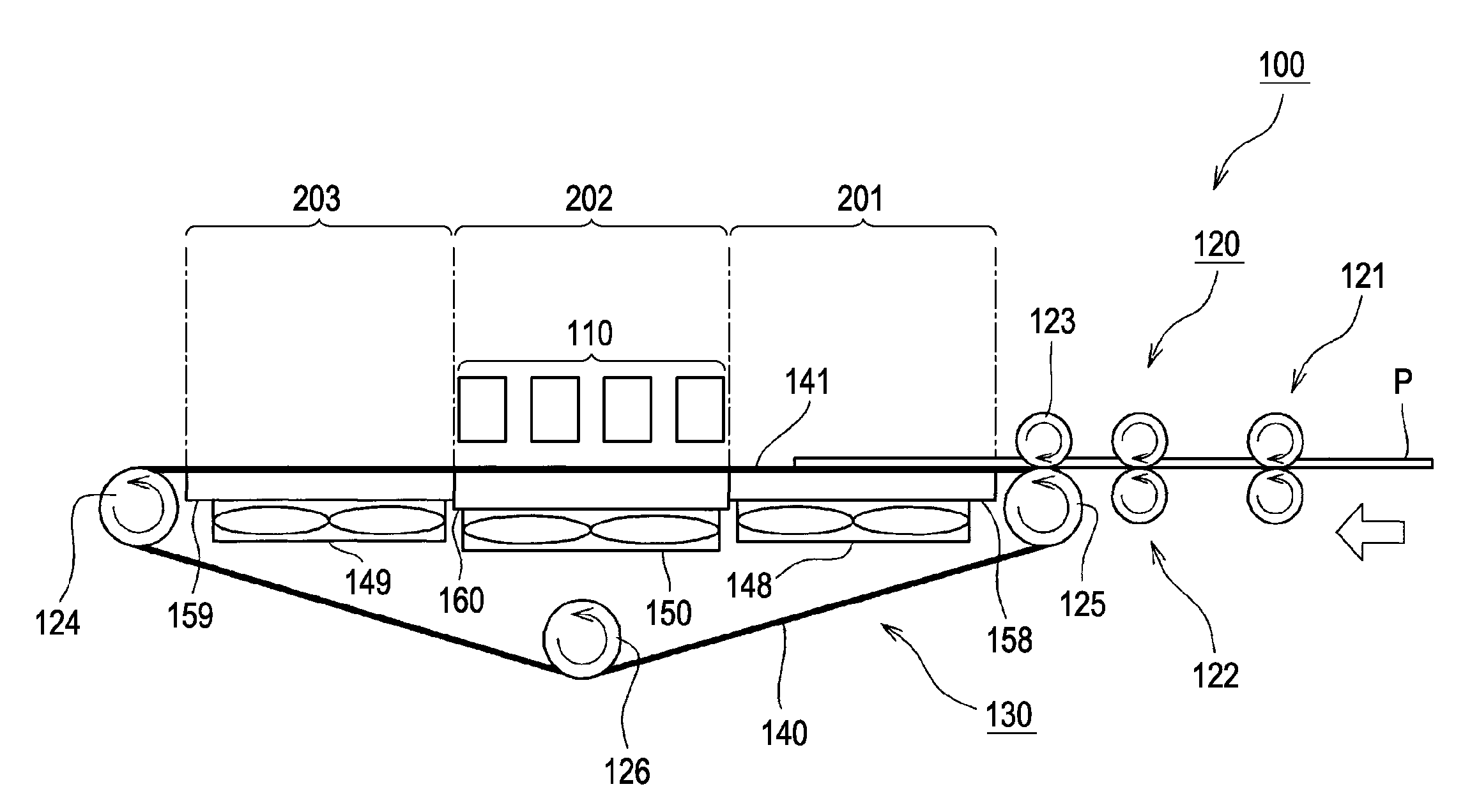
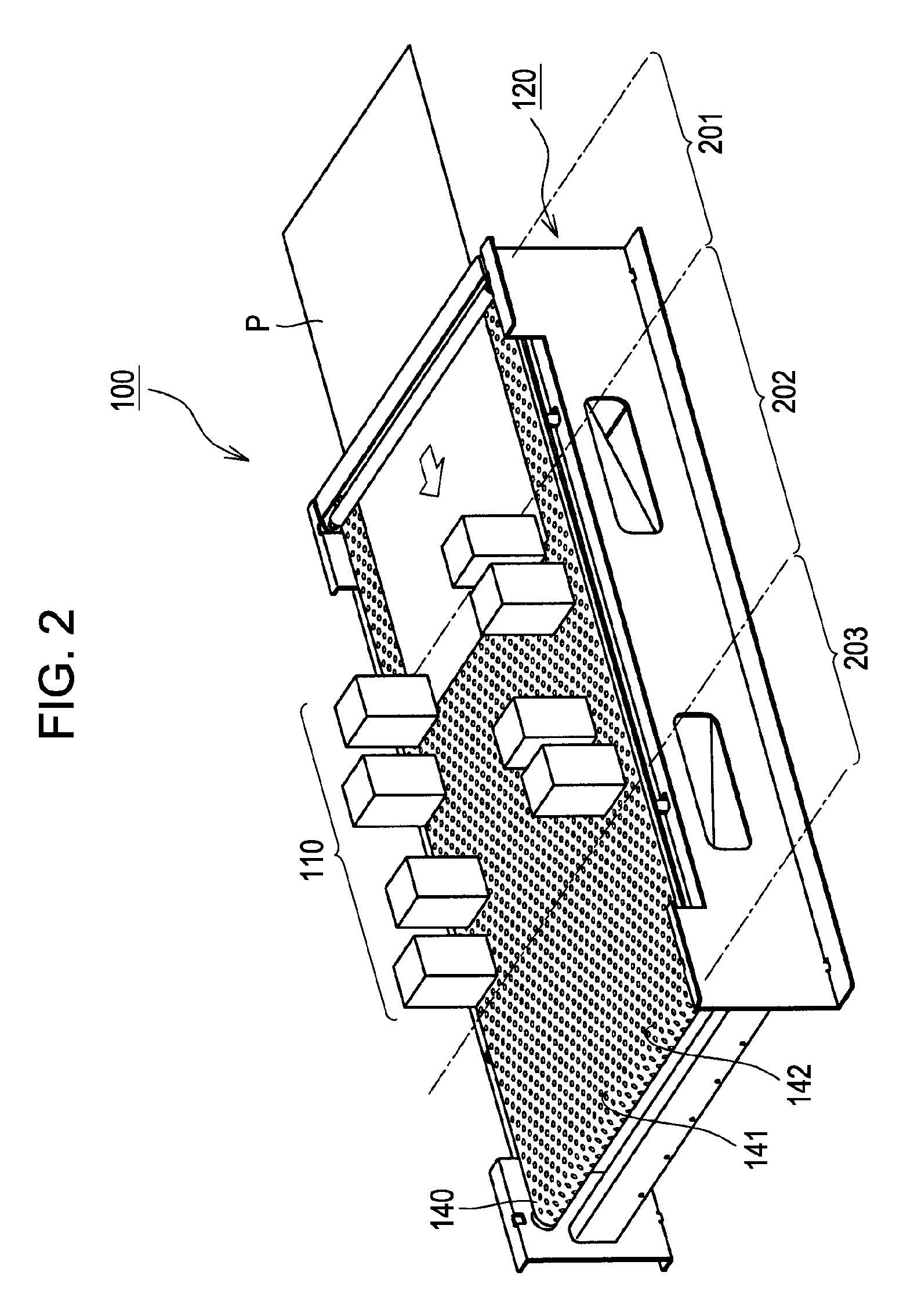
[0029]FIG. 1 is a side view illustrating the schematic structure of an ink jet recording device 100 according to this embodiment. As illustrated in the drawing, the recording device 100 has a transport unit 120 which transports a sheet P as a recording medium and plural recording heads 110 which eject ink onto the sheet P to perform a recording operation.

[0030]The transport unit 120 has a drive roller 124, driven rollers 125 and 126 and an endless transport belt 140 as a transport member extended over the rollers. The drive roller 124 and the driven roller 125 are substantially horizontally arranged. The driven roller 126 is arranged below a middle position in-between the drive roller 124 and the driven roller 125. That i...


PUM


Abstract

A recording device includes: a first suction unit which has a support member for supporting a recording medium and a plurality of suction holes provided in the support member to support the recording medium under control that a second suction force of the suction holes not covered by the recording medium is restricted to be smaller than a first suction force of the suction holes covered by the recording medium; a recording head which performs recording on the recording medium supported by the first suction unit.

Description

BACKGROUND[0001]1. Technical Field[0002]The present invention relates to a recording device, and more particularly, to a recording device which performs recording by ejecting ink onto a recording medium sucked and transported on a transport member.[0003]2. Related Art[0004]There has been known a recording device using an ink jet recording head (see JP-A-10-315551). In the recording device, a recording medium is sucked onto a transport belt by a suction force of through holes formed in the transport belt to be transported to a recording area. In this manner, floating of the recording medium from the transport belt is suppressed.[0005]However, in the recording device, airflow is generated by the suction force of the through holes not blocked by the recording medium in the recording area of the recording head. The air flow affects a flight state of ink droplets. When the suction force of the through holes is decreased to stabilize the flight state of ink droplets, the floating of the r...

Claims


Application Information

Patent Timeline
Patent Type & Authority Patents(United States)
IPC IPC(8): B41J2/01
CPCB41J11/007B41J11/0085
Inventor SAWADA, KEISHI
Owner SEIKO EPSON CORP
Why Eureka
Try Eureka