Power transmission control apparatus, power transmission apparatus, contactless power transmission system, and data determination method

a power transmission apparatus and control apparatus technology, applied in the direction of battery data exchange, transmission, transportation and packaging, etc., can solve the problems of inability to reliably and rapidly perform a bit synchronization process, data transmitted from the power reception apparatus cannot be determined correctly, periodic authentication data transmitted from the power reception apparatus no longer reaches the power transmission apparatus, etc., to achieve the effect of simplifying the data determination processing circuit, and reducing the cost of operation

Active Publication Date: 2012-05-15
138 EAST LCD ADVANCEMENTS LTD
View PDF6 Cites 10 Cited by
  • Summary
  • Abstract
  • Description
  • Claims
  • Application Information

AI Technical Summary

Benefits of technology

[0019]An advantage of the invention is to provide a power transmission apparatus that is included in a contactless power transmission system, is allowed to reliably and rapidly perform a bit synchronization (initial synchronization) process, a first-received periodic authentication data determination process, or the like, and has a simplified data determination processing circuit. Another advantage of the invention is to provide a power transmission apparatus that is included in a contactless power transmission system, and is allowed to receive periodic authentication data and a communication packet transmitted from a power reception apparatus, as distinguished from each other.
[0020]A power transmission control apparatus according to a first aspect of the invention is a power transmission control apparatus provided in a power transmission apparatus included in a contactless power transmission system where power is transmitted from the power transmission apparatus to a power reception apparatus by electromagnetically coupling a primary coil and a secondary coil. The power transmission control apparatus includes: a signal detection circuit that detects a signal induced in the primary coil; and a power transmission control circuit that determines a value of transmission data transmitted from the power reception apparatus by a load modulation, on the basis of an output signal of the signal detection circuit. The power transmission control circuit obtains detection data by detecting the transmission data on the basis of the output signal of the signal detection circuit at every drive clock cycle of the primary coil. If a value of the detection value is identical n-times continuously, where n=m+α≦p, the m is an integer equal to or larger than 0, the α is an integer equal to or larger than 1, and the p is an integer equal to or larger than 1, the power transmission control circuit determines that the value of the transmission data transmitted by the power reception apparatus is the value of the detection data.
[0021]In the contactless power transmission system, the power transmission apparatus AC-drives the primary coil using a drive clock. The power reception apparatus regenerates the drive clock of the primary coil, for example, by shaping the waveform of a sinusoidal signal obtained from the secondary coil end, and turns on or off a load modulation transistor of a load modulation unit in synchronization with the regenerated drive clock so as to change the state of a load of the power reception apparatus. Thus, “0” or “1” is transmitted from the power reception apparatus to the power transmission apparatus. That is, the power reception apparatus modulates the load using the drive clock of the primary coil as a timing reference so as to transmit transmission data to the power transmission apparatus.
[0022]As for communications using load modulation, it is preferable that a communication rule such as one where one-bit data (“0” or “1”) continues over a period corresponding to p drive clocks be stipulated.
[0023]The power transmission control apparatus included in the power transmission apparatus determines the value (“0” or “1”) of data transmitted from the power reception apparatus by the load modulation, on the basis of an output signal of the signal detection circuit (including, for example, a waveform detection circuit). A period over which one-bit data, “0” or “1”, transmitted from the power reception apparatus to the power transmission apparatus continues is set to k-times (k is an integer equal to or larger than 1) a period corresponding to p (p is an integer equal to or larger than 2) drive clocks of the primary coil. For example, if p=16 and k=1, the data length of one bit corresponds to 16 drive clocks of the primary coil. For example, if p=16 and k=2, the data length of one bit corresponds to 32 drive clocks of the primary coil.
[0024]A problem caused when the power transmission control apparatus determines whether received data (that is, transmission data transmitted from the power reception apparatus by the load modulation) is “0” or “1” is the existence of a data-undetermined period. Specifically, when the power reception apparatus modulates the load thereof to change the load state, there exists a data-undetermined period that continues from the timing when the load state of the power reception apparatus has been changed to a time when the power transmission apparatus can stably detect the change in the load state of the power reception apparatus and that corresponds to m (m is an integer equal to or larger than 0) drive clocks of the primary coil. For example, when the power reception apparatus modulates the load to change the value of transmission data from “0” to “1”, a lapse of a certain length of time is required until the level of the coil end signal (e.g., coil end voltage) of the primary coil is changed from a level corresponding to “0” to a level corresponding to “1”. During a data-undetermined period, a signal (coil end signal) obtained from the coil end of the primary coil is unstable and is less reliable. Therefore, if it is determined whether transmission data is “0” or “1”, on the basis of only received data obtained during a data-undetermined period, there is a high possibility that an erroneous determination is made.

Problems solved by technology

However, if an erroneous timing is obtained by performing bit synchronization (initial synchronization), data transmitted from the power reception apparatus can no longer be determined correctly.
Specifically, once a takeover state occurs, periodic authentication data transmitted from the power reception apparatus no longer reaches the power transmission apparatus.
However, the power transmission apparatus of the contactless power transmission system according to the related-art example cannot reliably and rapidly perform a bit synchronization (initial synchronization) process and, for example, a process of determining first received periodic authentication data.
A problem caused when the power transmission control apparatus determines whether received data (that is, transmission data transmitted from the power reception apparatus by the load modulation) is “0” or “1” is the existence of a data-undetermined period.
During a data-undetermined period, a signal (coil end signal) obtained from the coil end of the primary coil is unstable and is less reliable.
Therefore, if it is determined whether transmission data is “0” or “1”, on the basis of only received data obtained during a data-undetermined period, there is a high possibility that an erroneous determination is made.
However, if the power transmission control apparatus always performs n-times continuous matching determinations, the time required for the determined process is increased and the processing load put on the determination circuit is increased.
Therefore, if n=6 (therefore, α=1), the reliability of data determinations is not sufficiently ensured.
However, there occur adverse effects that the processing time required to determine data is increased and the determination circuit is complicated.

Method used


Image

  • Power transmission control apparatus, power transmission apparatus, contactless power transmission system, and data determination method
  • Power transmission control apparatus, power transmission apparatus, contactless power transmission system, and data determination method
  • Power transmission control apparatus, power transmission apparatus, contactless power transmission system, and data determination method

Examples


Embodiment Construction

[0078]Now, a preferred embodiment of the invention will be described in detail. The embodiment described below does not unduly limit the invention as set forth in the appended claims. Also, not all the configurations described in the embodiment are essential as means for solving the above-mentioned problems.

[0079]Configurations of Electronic Apparatuses

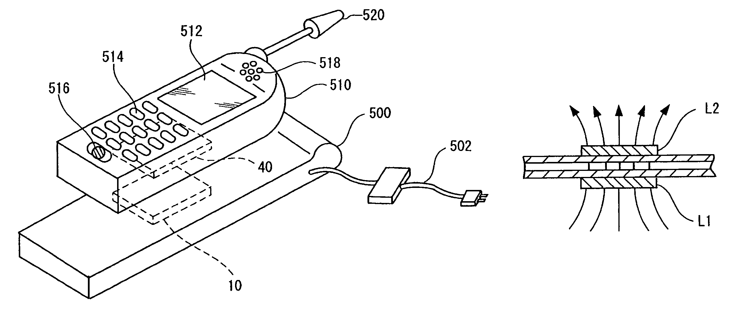
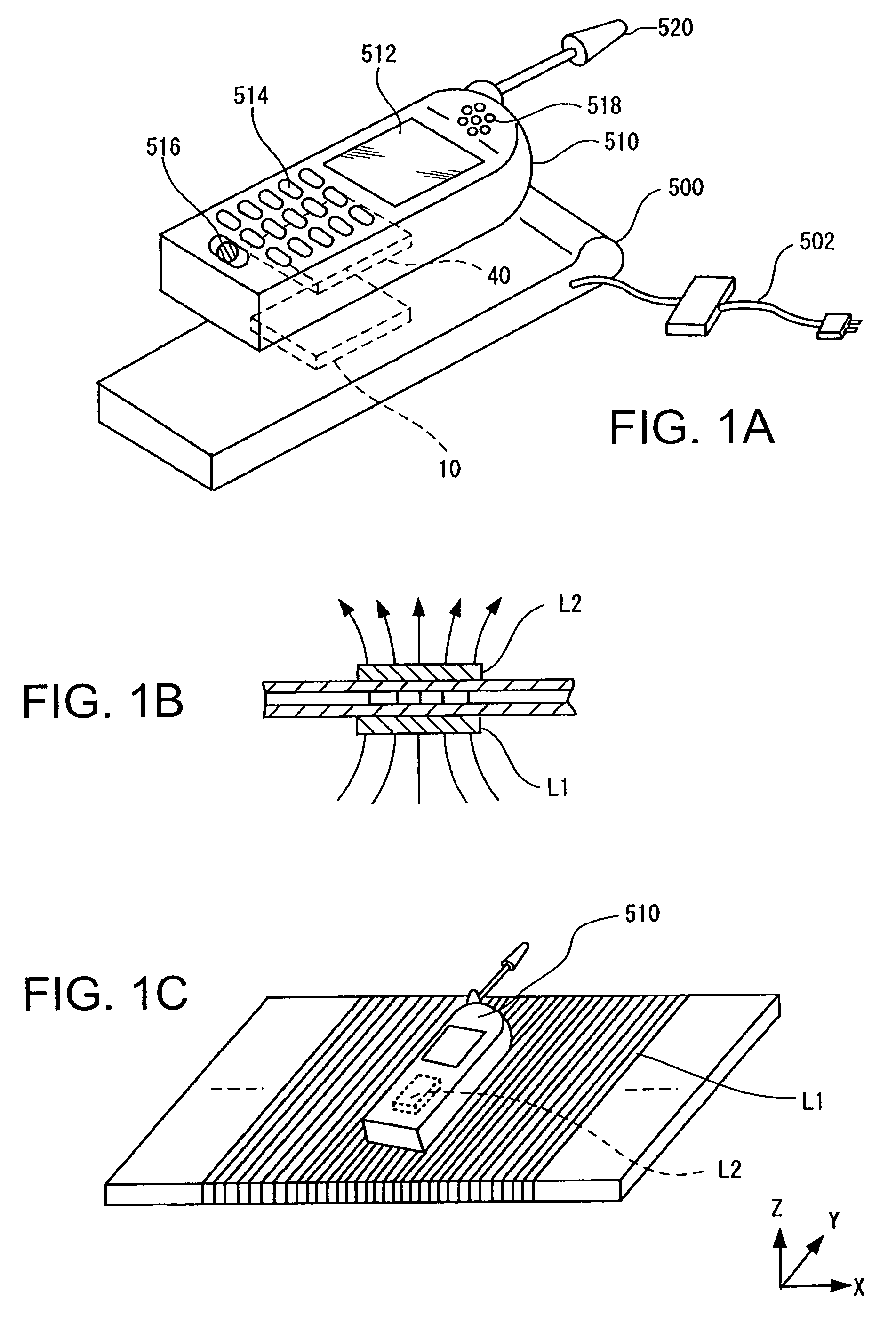
[0080]FIGS. 1A to 1C are drawings showing an example configuration of a contactless power transmission system. FIG. 1A shows an example of an electronic apparatus to which a contactless power transmission method according to this embodiment is applied. A charger 500 (cradle), which is an example of an electronic apparatus, includes a power transmission apparatus 10. A cell phone 510, which is an example of an electronic apparatus, includes a power reception apparatus 40. The cell phone 510 includes a display unit 512 such as a liquid crystal display (LCD), an operation unit 514 including buttons and the like, a microphone 516 (audio i...


PUM


Abstract

A power transmission control apparatus is a power transmission control apparatus provided in a power transmission apparatus included in a contactless power transmission system where power is transmitted from the power transmission apparatus to a power reception apparatus by electromagnetically coupling a primary coil and a secondary coil. The power transmission control apparatus includes: a signal detection circuit that detects a signal induced by the primary coil; and a power transmission control circuit that determines a value of transmission data transmitted from the power reception apparatus by a load modulation, on the basis of an output signal of the signal detection circuit. The power transmission control circuit obtains detection data by detecting the transmission data on the basis of the output signal of the signal detection circuit at every drive clock cycle of the primary coil. If a value of the detection value is identical n-times continuously, where n=m+α≦p, the m is an integer equal to or larger than 0, the α is an integer equal to or larger than 1, and the p is an integer equal to or larger than 1, the power transmission control circuit determines that the value of the transmission data transmitted by the power reception apparatus is the value of the detection data.

Description

BACKGROUND[0001]1. Technical Field[0002]The present invention relates to a power transmission control apparatus, a power transmission apparatus, a contactless power transmission system, and a data determination method.[0003]2. Related Art[0004]Contactless power transmission that uses electromagnetic induction to transmit power without using a metal contact has come under the spotlight. As applications of contactless power transmission, charging of a cell phone, charging of a home appliance (e.g., a handset), and the like have been proposed.[0005]A contactless power transmission apparatus using a primary coil and a secondary coil is described, for example, in JP-A-2006-60909. In the contactless power transmission system described in JP-A-2006-60909, a power transmission apparatus transmits data to a power reception apparatus by a frequency modulation. Also, the power reception apparatus transmits data to the power transmission apparatus by a load modulation.[0006]The power reception ...

Claims


Application Information

Patent Timeline
Patent Type & Authority Patents(United States)
IPC IPC(8): H02J7/00
CPCH02J7/025H02J7/00045H02J7/0044H02J50/80H02J50/12H02J50/60
Inventor SHIOZAKI, NOBUTAKAONISHI, KOTAKAMIYAMA, MASAYUKI
Owner 138 EAST LCD ADVANCEMENTS LTD
Why Eureka
Try Eureka