Measurement of speed or vibration characteristics using a LIDAR device with heterodyne detection

a technology of heterodyne detection and measurement of speed or vibration characteristics, which is applied in the direction of liquid/fluent solid measurement, devices using optical means, reradiation, etc., can solve the problems of difficult movement, interfere with or prevent the detection of the wave portion, and is not suitable for use on board a vehicle or an aircraft. , to achieve the effect of only slightly modifying such devices

Active Publication Date: 2012-05-15
OFFICE NAT DETUDES & DE RECH AEROSPATIALES
View PDF22 Cites 8 Cited by
  • Summary
  • Abstract
  • Description
  • Claims
  • Application Information

AI Technical Summary

Benefits of technology

[0037]It also has the advantages provided by the accumulation of analysis results or detection results, in particular for separating the information useful for measurement from the variable and incoherent noise which is also detected during the measurement cycle.
[0038]In addition, applying shifts which vary from one time slot to the next, to the phase characteristic of the optical wave, improves the spatial resolution in the pointing direction of the monostatic device. Typically, the invention produces a spatial resolution for measurements, along the pointing direction, which is of the order of C×Tmod / 2, where C is the propagation speed of the optical wave, and Tmod is the individual duration of the modulation time slots corresponding to the successive factors q.
[0062]Such a LIDAR device of the invention can easily be obtained by appropriately modifying or programming a prior art device.

Problems solved by technology

However, the scattered wave which is collected may originate not only from the object in the target volume which the LIDAR device is pointing towards, but also from objects outside the target volume which may also significantly scatter the optical wave.
In this case, the presence of the cloud in the background, and possibly the motion of the cloud, can interfere with or prevent the detection of the portion of the wave which is scattered by the content of the target volume.
They are therefore poorly suited for use on board a vehicle or an aircraft, for example.
Usually they are difficult to move because of their structure involving several separate parts.
Bistatic LIDAR devices are also inappropriate for mapping speed measurements by varying the target volume within a much larger volume of analysis.
However, speed measurements obtained with such monostatic devices can be impeded and prevented by a backscattering element located in the direction in which the device is pointing, in front of or behind the target volume, even if the distance from the target volume is taken into account in the heterodyne detection.

Method used


Image

  • Measurement of speed or vibration characteristics using a LIDAR device with heterodyne detection
  • Measurement of speed or vibration characteristics using a LIDAR device with heterodyne detection
  • Measurement of speed or vibration characteristics using a LIDAR device with heterodyne detection

Examples


Embodiment Construction

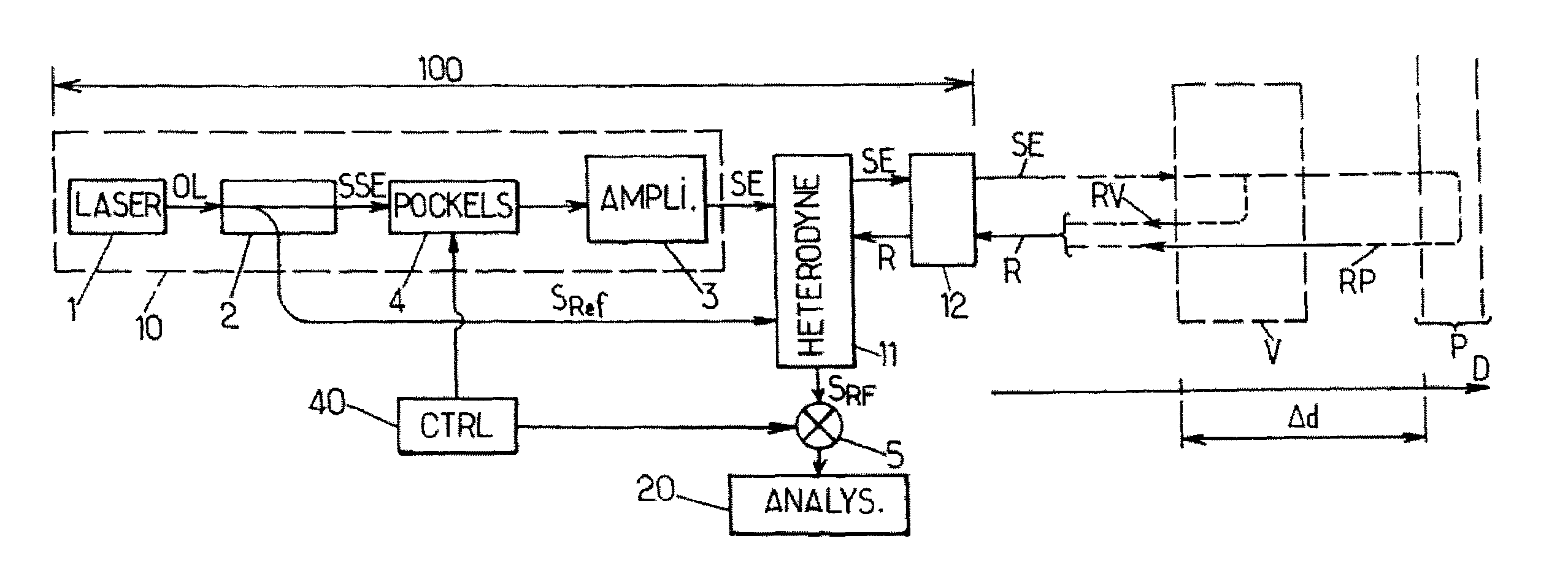
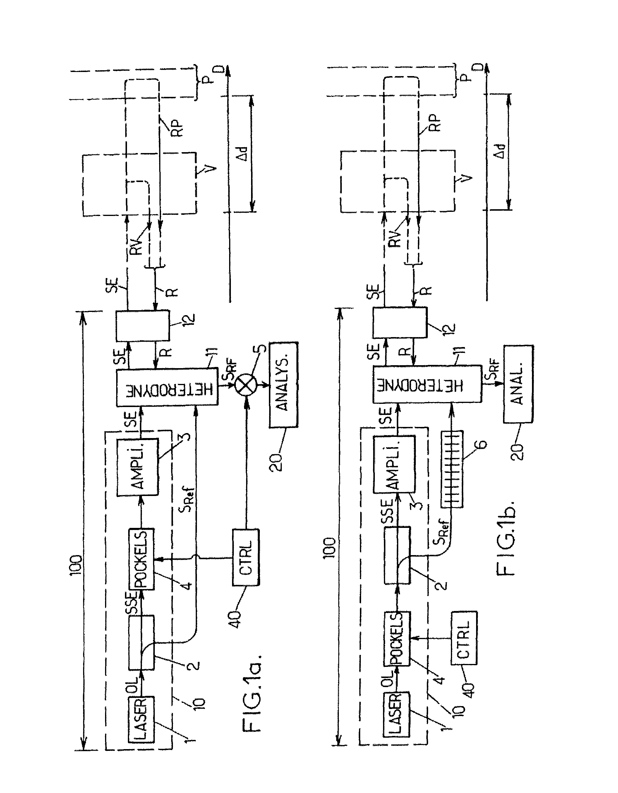
[0067]In FIGS. 1aand 1b, the same references denote identical elements or elements with identical functions. In addition, the following references denote the components indicated below, which are used in the same manner as in a known monostatic LIDAR device with heterodyne detection:[0068]100: the LIDAR device with heterodyne detection,[0069]1: a laser oscillator, adapted to produce an optical wave OL,[0070]2: an optical splitter, which is arranged to split the optical wave OL into an emission source signal SSE and a reference signal SRef,[0071]3: an optical amplifier, which is adapted to produce an emission signal SE from the emission source signal SSE,[0072]11: a mixing and detection unit,[0073]12: an optical head, adapted to transmit the emission signal SE in the direction of a target volume and to receive a backscattered signal R, and[0074]20: analysis means.

[0075]In addition, D denotes a pointing direction of the device 100, which is selected by the orientation of the optical h...


PUM


Abstract

A process for measuring speed or vibration characteristics using a LIDAR device allows the separation of a useful contribution and an interfering contribution in a backscattered signal. To this purpose, a phase characteristic of an optical wave emitted in the direction of a target volume is modulated. The interfering contribution, which originates from a source at a distance from the target volume, appears with variable shifts of said phase characteristic in a heterodyne detection signal. An accumulation then isolates the useful contribution, from which a result is obtained for the speed or vibration measurement. The process can be implemented with a frequency modulation or phase modulation of the optical wave.

Description

FIELD OF THE INVENTION[0001]This invention relates to the measurement of speed or vibration characteristics using a LIDAR device with heterodyne detection, also called coherent LIDAR. It concerns a process as well as a device for performing such a measurement.BACKGROUND OF THE INVENTION[0002]LIDAR (Light Detection and Ranging) devices are widely used in numerous detection and measurement applications. Such applications include wind speed measurement, fluid flow analyses, the study of vibration phenomena, vehicle speed measurement, applications in the field of air transport, etc. Their operation consists in emitting a coherent optical wave in the direction of a target volume where an object or a phenomenon to be studied is located, and to collect a portion of this wave which is backscattered from the target volume. In a coherent LIDAR device, the collected portion of the scattered wave undergoes heterodyne detection. The speed measurement is determined from a Doppler shift which is m...

Claims


Application Information

Patent Timeline
Patent Type & Authority Patents(United States)
IPC IPC(8): G01C3/08
CPCG01F1/661G01S17/58G01P5/26G01F1/663
Inventor VALLA, MATTHIEUBESSON, CLAUDINEAUGERE, BEATRICE
Owner OFFICE NAT DETUDES & DE RECH AEROSPATIALES
Why Eureka
Try Eureka