Protection switching method and apparatus for use in ring network

a protection switching and ring network technology, applied in the field of network technology, can solve the problems of increasing data traffic loss, delay in receiving a failure notification signal, and failure notification of designated master network devices, and achieve the effect of fast protection switching and fast protection switching

Inactive Publication Date: 2012-05-15
ELECTRONICS & TELECOMM RES INST
View PDF11 Cites 3 Cited by
  • Summary
  • Abstract
  • Description
  • Claims
  • Application Information

AI Technical Summary

Benefits of technology

[0010]The present invention provides a protection switching method and apparatus that can perform fast protection switching when a network failure occurs, more particularly, a protection switching method and apparatus that can perform fast protection switching when a unidirectional or bidirectional link failure occurs in a network device.

Problems solved by technology

Specifically, when a failure occurs in the system, a designated master network device may receive a failure notification from a network device on a packet transmission path.
However, when a path between the network device for providing the failure notification and the master network device is not a short distance, in the above-described method, reception of a failure notification signal may be delayed.
For this reason, there is a problem in that the loss of data traffic increases and the network performance decreases when the protection switching is delayed.
In particular, there is a problem in that the reception of a switching request signal according to the failure is further delayed when the failure occurs in a link farthest from the master network device.

Method used


Image

  • Protection switching method and apparatus for use in ring network
  • Protection switching method and apparatus for use in ring network
  • Protection switching method and apparatus for use in ring network

Examples


Embodiment Construction

[0026]The invention is described more fully hereinafter with reference to the accompanying drawings, in which exemplary embodiments of the invention are shown. This invention may, however, be embodied in many different forms and should not be construed as limited to the exemplary embodiments set forth herein. Rather, these exemplary embodiments are provided so that this disclosure is thorough, and will fully convey the scope of the invention to those skilled in the art. In the drawings, the size and relative sizes of layers and regions may be exaggerated for clarity. Like reference numerals in the drawings denote like elements.

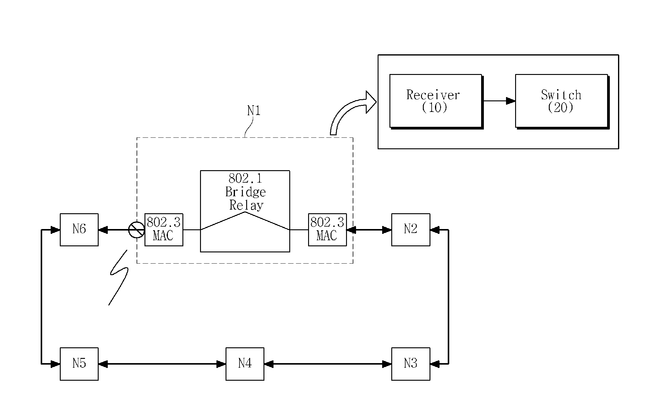
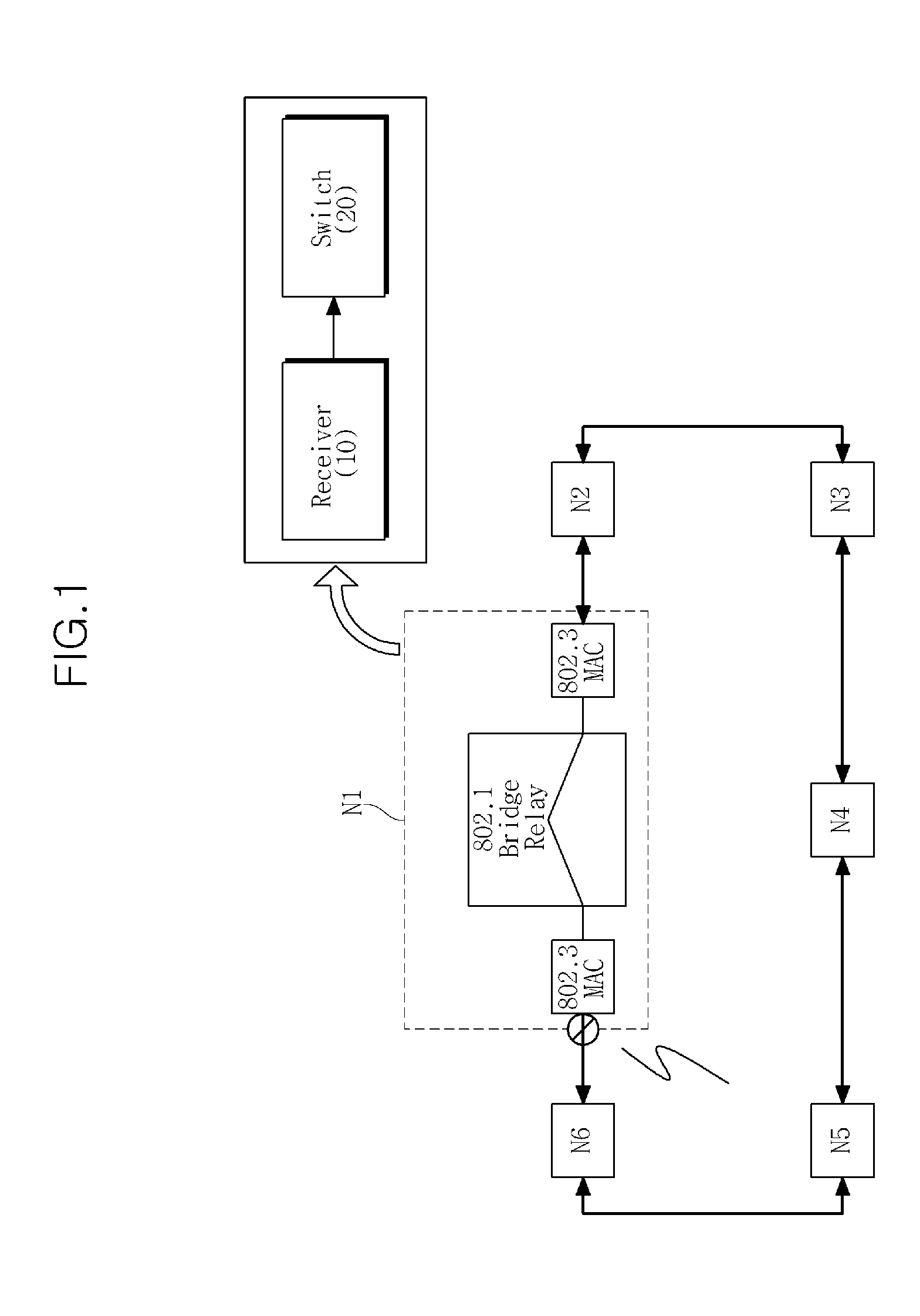
[0027]FIG. 1 is a block diagram showing a configuration of a network device according to an exemplary embodiment of the present invention.

[0028]Referring to FIG. 1, a network according to an exemplary embodiment of the present invention can be a closed network, that is, a ring network. Here, the network can be an Ethernet network.

[0029]The network is implement...


PUM


Abstract

A protection switching method and apparatus for use in a ring network are provided. At least two switching request signals are received from a network device neighboring a link in which a failure occurs. A switching operation is performed in response to a first received signal of the at least two received switching request signals. When a network failure occurs, fast protection switching can be performed.

Description

CROSS REFERENCE TO RELATED APPLICATIONS[0001]This application claims priority from Korean Patent Application No. 10-2007-0127873, filed on Dec. 10, 2007, the disclosure of which is incorporated herein in its entirety by reference.BACKGROUND OF THE INVENTION[0002]1. Field of the Invention[0003]The present invention relates to a network technology, and more particularly, to a network switching technology.[0004]This work was supported by the IT R&D program of Ministry of Information and Communication (MIC) / Institute for Information Technology Advancement (IITA) [2006-S-064-02, BcN Network Engineering].[0005]2. Description of the Related Art[0006]In general, data traffic in a network may be switched and protected when a failure occurs in a transmission section in which the traffic is sent. For example, when a protection link is designated and a network link failure occurs, the data traffic may be switched and sent through the designated protection link.[0007]Specifically, when a failure...

Claims


Application Information

Patent Timeline
Patent Type & Authority Patents(United States)
IPC IPC(8): H04L12/26
CPCH04L12/437H04L41/0668H04L12/28
Inventor CHUN, KYUNG-GYULEE, SOON-SEOK
Owner ELECTRONICS & TELECOMM RES INST
Why Eureka
Try Eureka