
Glove reinforcement and method thereof

a technology of gloves and articulating joints, applied in chemical protection, nuclear engineering, nuclear elements, etc., can solve the problems of severely restricting the bending movement of articulating joints, restricting the bending movement of fingers, and prone to bunching of gloves, etc., to reduce the restriction of fingers movement, improve the bending resistance, and improve the effect of articulation

Active Publication Date: 2012-05-22
FLAGSUIT
View PDF21 Cites 2 Cited by
  • Summary
  • Abstract
  • Description
  • Claims
  • Application Information

AI Technical Summary

Benefits of technology

"The present patent provides a glove reinforcement that reduces the restriction of movement of a user's fingers. The reinforcement is made up of one or more X-shaped patterns that are located on the dorsal and palmar surfaces of the glove. These patterns are formed by affixing reinforcements to the glove at specific points. The edges of the glove are attached to each other so that the reinforcements form an X-shaped pattern when projected on a plane of motion of an interphalangeal joint. The reinforcements are located on one or both sides of each interphalangeal joint of the user's fingers. This design allows for increased strength, resistance to wear, and enhanced coefficient of friction in the glove."

Problems solved by technology

Traditional methods used to construct and reinforce a glove have a tendency to restrict the bending movement of a user's fingers.
For example, an internally pressurized glove is manufactured to restrain against axial elongation and radial expansion however, traditional methods used to reinforce the gloves are prone to bunching and often prevent or severely limit articulating joints from bending.
Traditional internally pressurized gloves also lack the ability to resist internal pressure while allowing the interphalangeal joints in the finger to move freely which leads to rapid exhaustion of the energy of a user.
Traditional gloves also lack resistance to wear, have poor grip and are awkwardly shaped which reduces manual dexterity of the user.

Method used


Image

  • Glove reinforcement and method thereof
  • Glove reinforcement and method thereof
  • Glove reinforcement and method thereof

Examples


Embodiment Construction

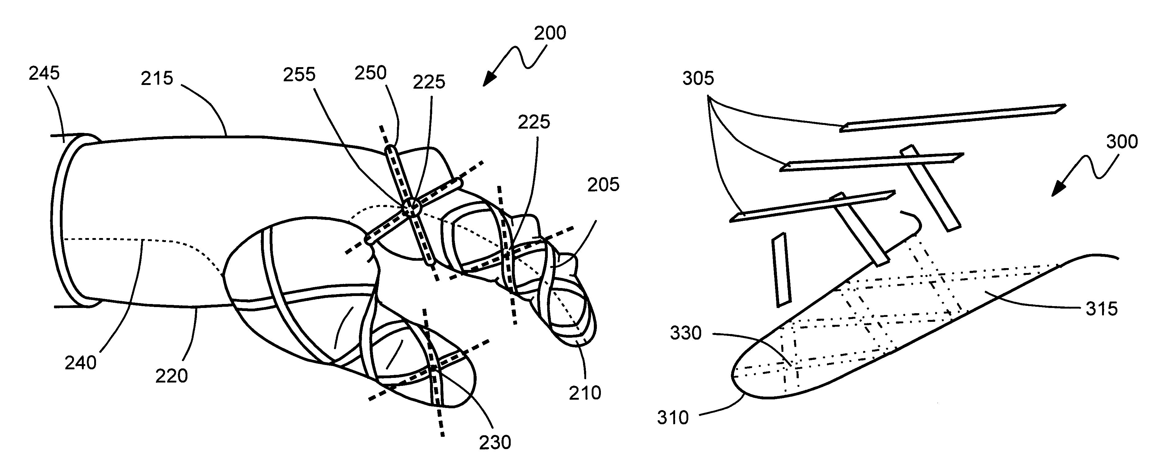
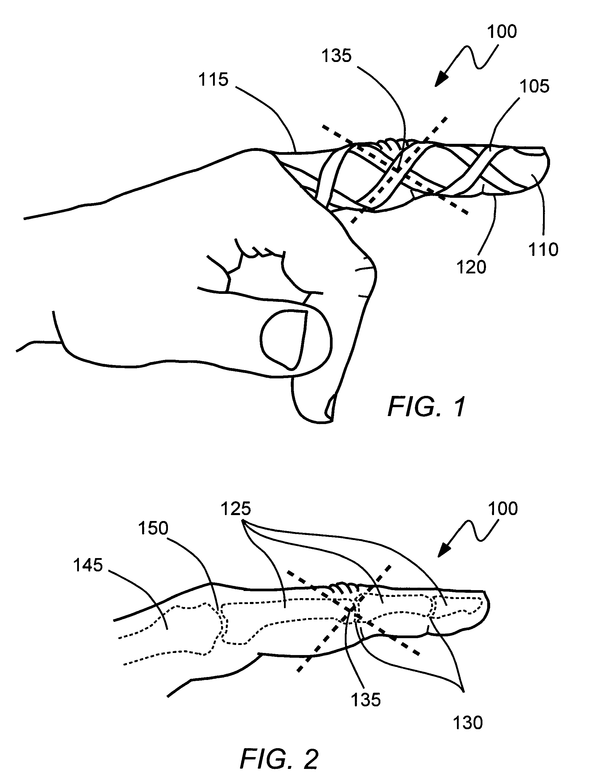
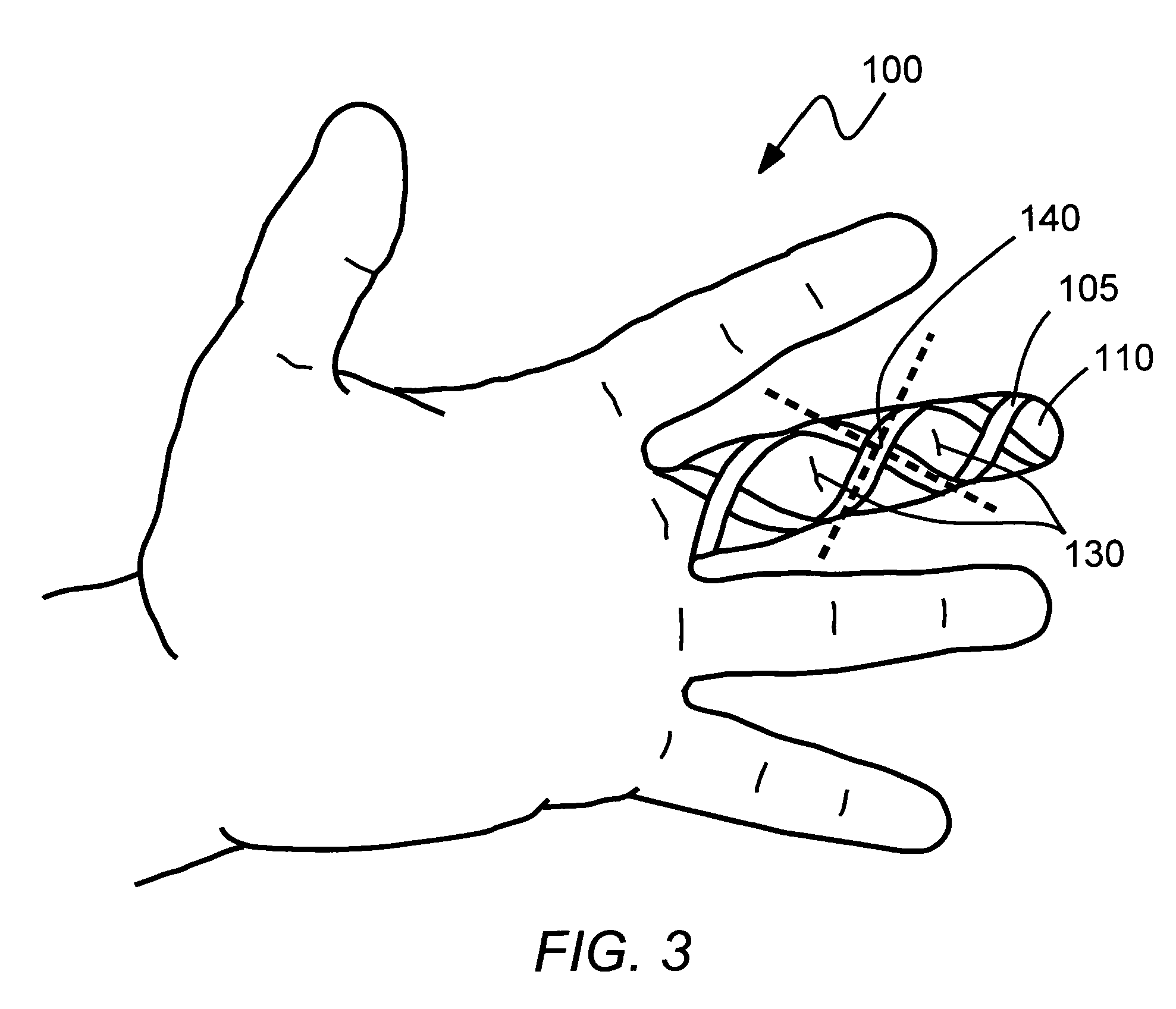
[0020]Referring to the drawings and, in particular, FIGS. 1-3, an arrangement of continuous reinforcements generally referred to by reference number 100 is shown. In an exemplary embodiment, reinforcements arrangement 100 has at least one reinforcement 105 affixed continuously to one or more fingers 110 of a glove (not shown). Finger 110 has a dorsal surface 115 and a palmar surface 120. Each finger 110 has three phalanges 125, or finger bones, while the thumb has two phalanges 125. Each finger and thumb has one metacarpal 145. An interphalangeal joint 130 separates each phalanx 125, and a metacarpophalangeal joint 150 separates each metacarpal 145 from the first phalanx 125.

[0021]As illustrated in FIGS. 1 and 2, reinforcement 105 is affixed continuously to the one or more fingers of a glove to form at least one X-shaped pattern 135 when projected on a plane of motion of interphalangeal joint 130. Reinforcement 105 is located on one or both sides of each interphalangeal joint 130. X...


PUM


Abstract

A glove having one or more reinforcements affixed thereon that reduce restriction of movement of fingers of a user. The reinforcements cross to form at least one X-shaped pattern when projected on a plane of motion of an interphalangeal joint of the fingers. The one or more reinforcements are located substantially on one or both sides of the interphalangeal joint of the fingers. The X-shaped pattern is substantially centered over an axis of rotation of the interphalangeal joint.

Description

CROSS REFERENCE TO RELATED PATENT APPLICATIONS[0001]The present application is a Utility application that claims priority of U.S. Provisional Application No. 60 / 915,444 filed on May 2, 2007. The provisional application is hereby incorporated herein by reference in its entirety.BACKGROUND OF THE INVENTION[0002]1. Field of the Invention[0003]The present disclosure relates to a glove reinforcement and a method of reinforcing a glove that enhances finger dexterity and reduces unfavorable restriction to movement.[0004]2. Description of Related Art[0005]Traditional methods used to construct and reinforce a glove have a tendency to restrict the bending movement of a user's fingers. For example, an internally pressurized glove is manufactured to restrain against axial elongation and radial expansion however, traditional methods used to reinforce the gloves are prone to bunching and often prevent or severely limit articulating joints from bending. Traditional internally pressurized gloves al...

Claims


Application Information

Patent Timeline
Patent Type & Authority Patents(United States)
IPC IPC(8): A41D19/00
CPCA41D13/065A41D13/08A41D19/01582
Inventor HOMER, PETER K.
Owner FLAGSUIT
Learn More