
Thermally insulated container

a container and thermal insulation technology, applied in the field of containers, can solve the problems of significant weight of portable containers, and none of these prior art patents have solved the needs of this ar

Active Publication Date: 2012-05-22
BLAKE MICHAEL N
View PDF39 Cites 36 Cited by
  • Summary
  • Abstract
  • Description
  • Claims
  • Application Information

AI Technical Summary

Benefits of technology

[0041]In one embodiment of the invention, a cylinder has a bore extending from the bottom wall and into the cavity. A shaft has a base end and a terminal end. The base end of the shaft engages the bore of the cylinder for securing the shaft to the container. An umbrella has a receiver and a canopy. The receiver of the umbrella engages the terminal end of the shaft. The first anchor and the second anchor prevent rotation of umbrella relative to the ground surface.
[0043]In another embodiment of the invention, the first side wall includes a first taper positioned adjacent to the bottom wall for increasing contact between the first side wall and the ground surface. The first taper includes a first bore for receiving a first stake. The second side wall includes a second taper positioned adjacent to the bottom wall for increasing contact between the second side wall and the ground surface. The second taper including a second bore for receiving a second stake. The third side wall including a third taper positioned adjacent to the bottom wall for increasing contact between the third side wall and the ground surface. The third taper including a third bore for receiving a third stake. The fourth side wall including a fourth taper positioned adjacent to the bottom wall for increasing contact between the fourth side wall and the ground surface. The fourth taper including a fourth bore for receiving a fourth stake. The first taper, the second taper, the third taper and the fourth taper prevent rotation of container relative to the ground surface. The first stake, the second stake, the third stake and the fourth stake engage the soil layer for preventing rotation of container relative to the ground surface.

Problems solved by technology

Since an individual is only capable of lifting and carrying a limited weight, the weight of the portable container is significant.
Although the aforementioned prior art have contributed to the development of the art of portable container, none of these prior art patents have solved the needs of this art.

Method used


Image

  • Thermally insulated container
  • Thermally insulated container
  • Thermally insulated container

Examples


Embodiment Construction

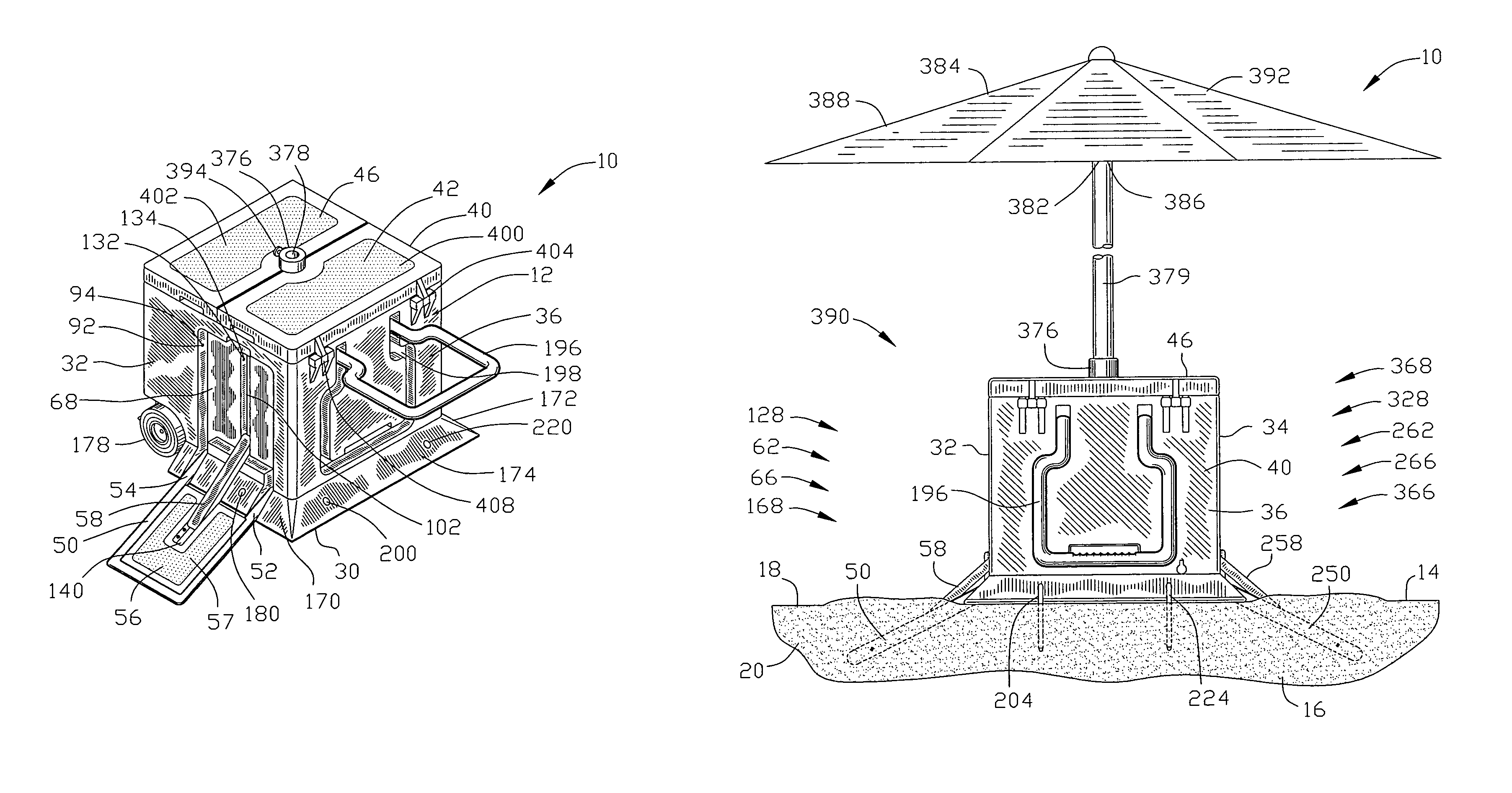
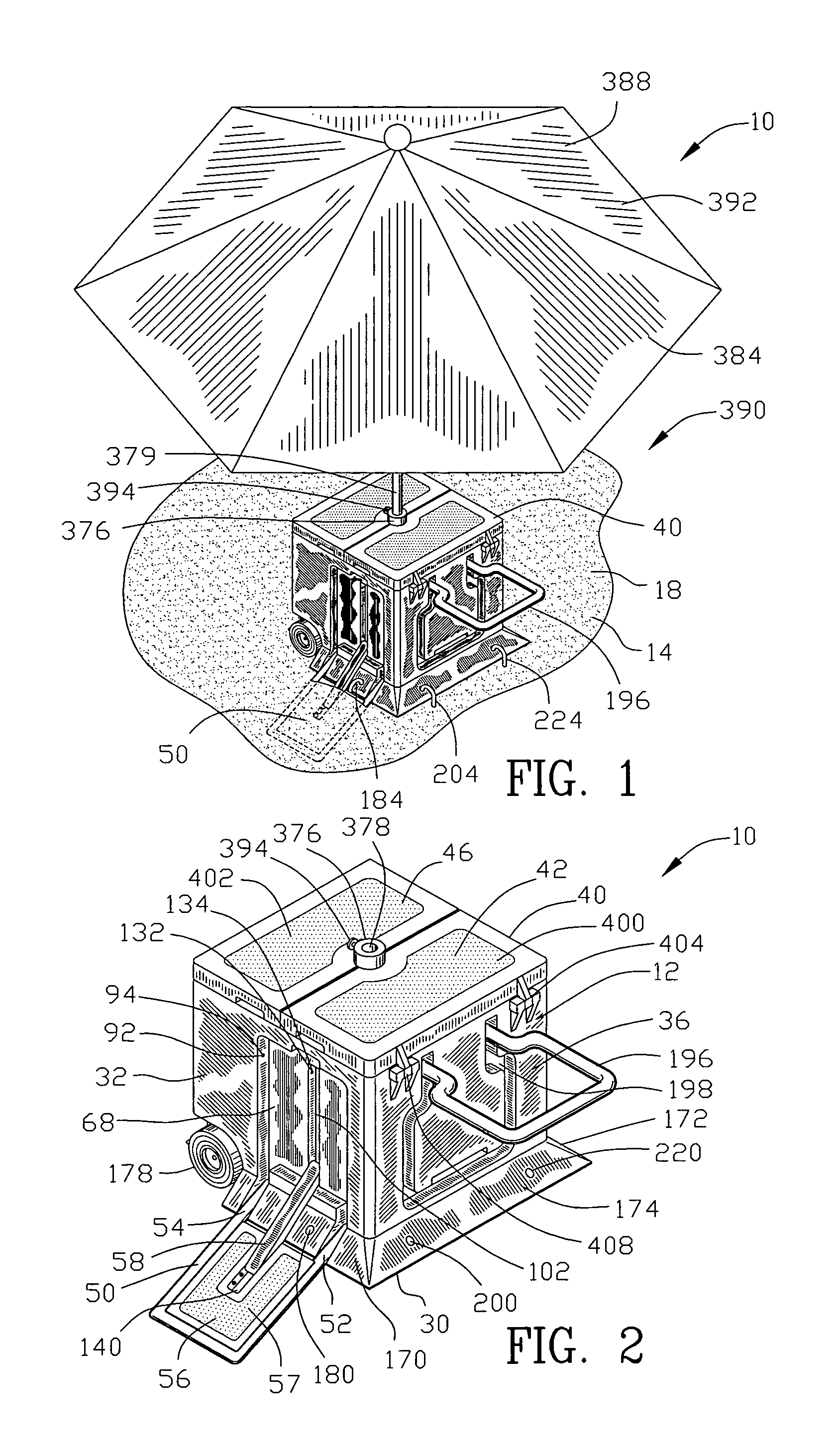
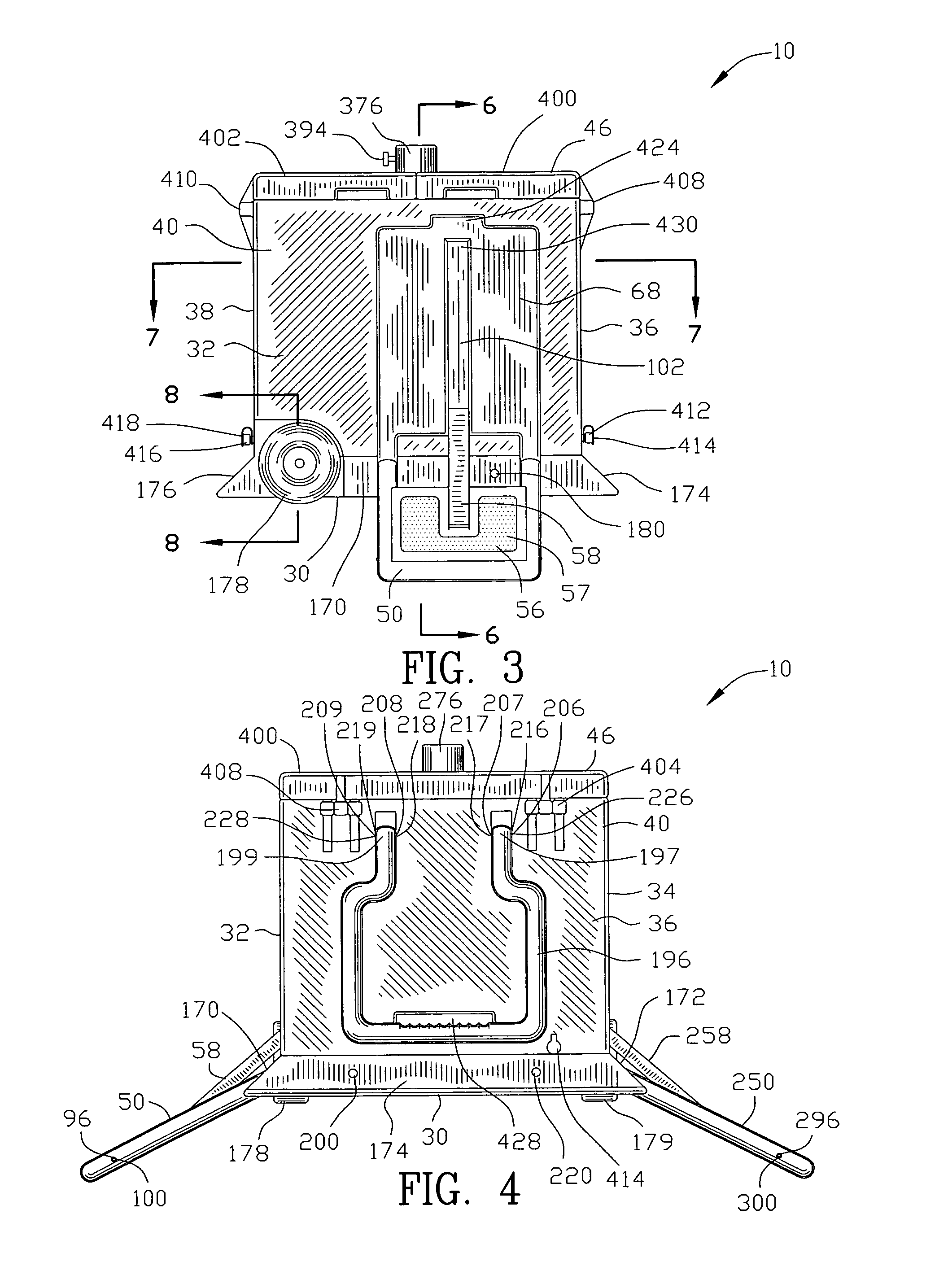
[0078]FIGS. 1-29 are various views of a thermally insulated container 10 for maintaining the thermo energy of an object 12. The thermo storage device 10 is positioned over a ground surface 14. The ground surface 14 covers a soil layer 16. The ground surface 14 is shown to be a sand surface 18 and the soil layer 16 is also shown to be a sand layer 20 as located predominantly at a beach. However, the ground surface 14 and the soil layer 16 may include other ground surfaces and soil layers.

[0079]The thermally insulated container 10 comprises a bottom wall 30, a first side wall 32, a second side wall 34, a third side wall 36 and a fourth side wall 38 for defining a container 40. The container 40 defines a cavity 42 for housing the object 12 and an aperture 44 for positioning the object 12 within the cavity 42. A cover plate 46 engages the aperture 44 for covering the cavity 42.

[0080]A first anchor 50 is pivotably secured to the first side wall 32. The first anchor 50 pivots from a posit...


PUM


Abstract

A thermally insulated container is disclosed for maintaining thermo energy of an object. A first anchor is pivotably secured to the container and pivots to a position below the container for engaging a soil layer and preventing rotation of the container relative to a ground surface. A first locking arm extends between the container and the first anchor for locking the first anchor relative to the container. A second anchor is pivotably secured to the container and pivots to a position below the container for engaging a soil layer and preventing rotation of the container relative to the ground surface. A second locking arm extends between the container and the second anchor for locking the second anchor relative to the container.

Description

CROSS-REFERENCE TO RELATED APPLICATIONS[0001]This application claims benefit of U.S. Patent Provisional application Ser. No. 61 / 069,371 filed Mar. 14, 2008. All subject matter set forth in provisional application Ser. No. 61 / 069,371 is hereby incorporated by reference into the present application as if fully set forth herein.BACKGROUND OF THE INVENTION[0002]1. Field of the Invention[0003]This invention relates to containers and more particularly to the thermally insulated containers.[0004]2. Background of the Invention[0005]In order for an individual to transport one or more articles a portable container may be utilized. Since an individual is only capable of lifting and carrying a limited weight, the weight of the portable container is significant. In addition, the carrying mechanism utilized with the portable container can greatly increase both the weight capacity of the portable container and the efficiently of the individual to lift and carry the portable container. More importa...

Claims


Application Information

Patent Timeline
IPC IPC(8): B65D25/22
CPCA45B23/00A45C11/20A45C15/00A45F3/44A47B91/02A45B2200/1054A45B2200/1063A47B31/00A47B95/02A47B2031/008
Inventor BLAKE, MICHAEL N.
Owner BLAKE MICHAEL N
Learn More