Device for unloading trays using a pivot member

a technology of pivot member and unloading tray, which is applied in the direction of sorting, special packaging, packaging of goods, etc., can solve the problems of slowed down rate of throughput of machine, raise certain problems, etc., and achieve the effect of reducing the workload of the operator, avoiding manual unloading tasks, and reducing the action of the operator

Inactive Publication Date: 2012-05-22
SOLYSTIC
View PDF3 Cites 3 Cited by
  • Summary
  • Abstract
  • Description
  • Claims
  • Application Information

AI Technical Summary

Benefits of technology

[0010]An object of the invention is to propose another device for automatically unloading a tray filled with flat articles, e.g. mailpieces, that is automated so as to help an operator, so as to reduce the workload of the operator, and so as to avoid manual unloading tasks that are arduous for the operator. In addition, another object of the invention is to propose a device for unloading a tray filled with flat articles that transfers the flat articles semi-automatically from a tray transfer system to a feed magazine with both reduced action from the operator and also a high rate of unloaded trays.
[0016]With such an arrangement, parallel mail handling is performed with it being possible to achieve an unloading rate of 6 trays per minute.

Problems solved by technology

The use of such unloading systems raises certain problems.
For example, the trays must be transferred manually from the unloading point of the unloading system, and that is an arduous and tiring task for the operator in view of the weights of the trays and of the mailpieces, and of the distance to go along the conveyor for unloading each tray.
In addition, the rate of throughput of the machine is slowed down because the operator cannot feed the feed magazine as quickly as would be necessary to keep up with the speed of the feed magazine.

Method used


Image

  • Device for unloading trays using a pivot member
  • Device for unloading trays using a pivot member
  • Device for unloading trays using a pivot member

Examples


Embodiment Construction

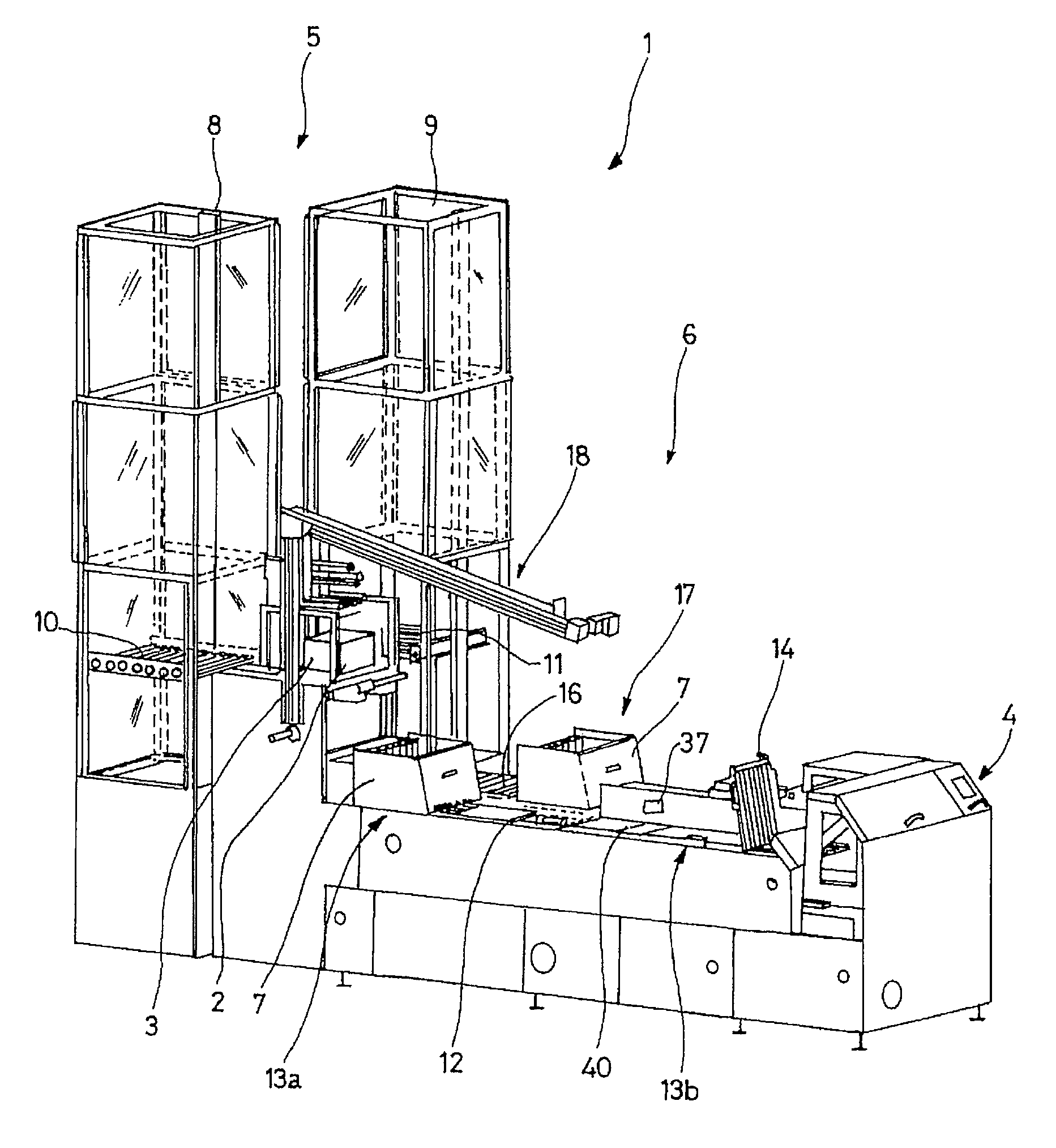
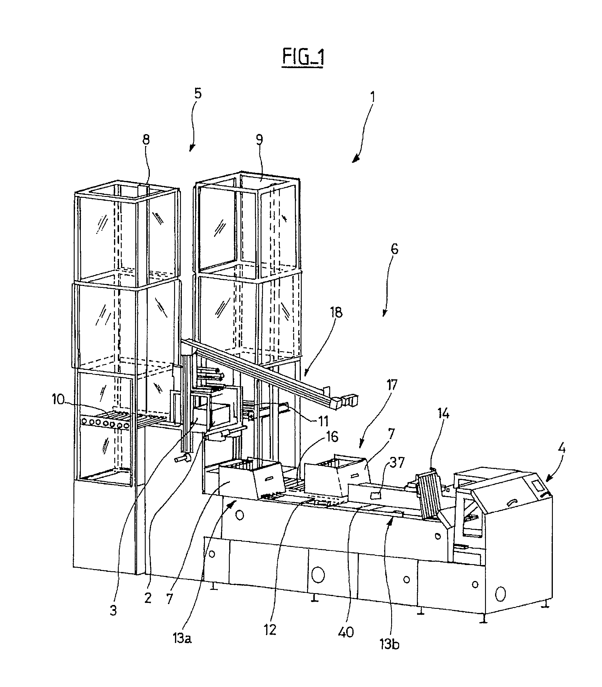
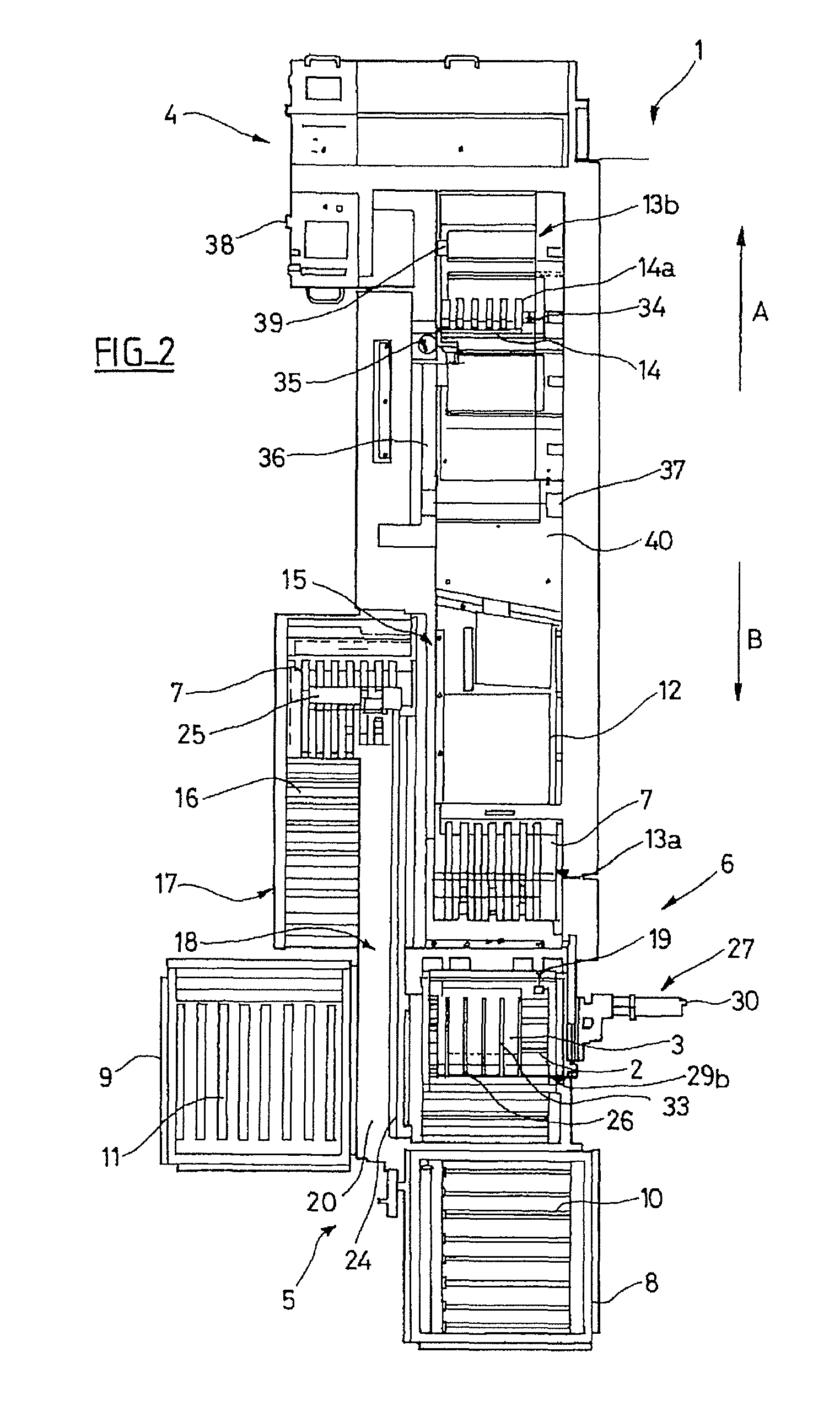
[0055]FIG. 1 shows a handling system1 of the invention for handling flat articles, e.g. mailpieces 3, stored in horizontal stacks in trays 2. The handling system includes a feed magazine 4 of a sorting machine and a tray transfer system 5. The tray transfer system 5 is arranged to feed the full trays back from the outlets to the inlet of the machine. In particular, for example, it is arranged to cause full trays 2 to be brought automatically from the sorting outlets (not shown) of the sorting machine to the feed magazine 4 where said trays are unloaded, and to cause empty trays 2 that have been unloaded into the feed magazine 4 of the machine to be brought automatically to the sorting outlets. It can be understood that this tray transfer system also has an inlet for being loaded with full trays coming from outside the machine, which full trays are brought to the feed magazine, and also has an inlet for being loaded with empty trays also coming from outside the machine, which empty t...


PUM

PropertyMeasurementUnit
thicknessesaaaaaaaaaa
weightsaaaaaaaaaa
speedaaaaaaaaaa

Abstract

The device for unloading an open-top tray filled with flat articles placed in a stack on the bottom of the tray comprises a pivot member suitable for taking hold of the tray and for tilting its opening downwards. The device further comprises: a pusher for holding the flat articles at the bottom of the tray when the tray is tilted; a shuttle box moved by a conveyor between the pivot member and a box unloading zone remote from the pivot member, the shuttle box having a bottom with back and front walls that are retractable or removable relative to the bottom; a box tilting device for tilting the box into a tilted position immediately below the tray; and a moving paddle mounted to be moveable vertically and horizontally, and designed in such a manner as to retract the front wall of the box and as to be inserted between the back wall of the box and the stack of flat articles.

Description

CROSS-REFERENCE TO RELATED APPLICATIONS[0001]This application is a 35 U.S.C. 371 National Phase Application from PCT / FR2008 / 052070, filed Nov. 18, 2008, and designating the United States, which claims the benefit of U.S. Provisional Application No. 60 / 988,932, filed Nov. 19, 2007.BACKGROUND OF THE INVENTION[0002]1. Field of the Invention[0003]The invention relates to a device for unloading an open-top tray filled with flat articles, e.g. mailpieces, that are placed in a stack on the bottom of the tray, the device including a pivot member suitable for taking hold of the tray and for tilting its opening downwards.[0004]2. Discussion of the Background Art[0005]In general, during a mail sorting process, the mailpieces are transported in stacks inside trays by conveyors, and they are unloaded by an operator at a Tray Unloading Device (TUD). For example, the trays are brought from the sorting outlets of a sorting machine or from the outside towards the tray unloading device where the mail...

Claims


Application Information

Patent Timeline
Patent Type & Authority Patents(United States)
IPC IPC(8): B65B21/02
CPCB07C1/025B65G65/23B65H2301/422542B65H2701/1916
Inventor CARTAL, BRUNOMADAR, FRANCOISGOOD, MATTHEW
Owner SOLYSTIC
Why Eureka
Try Eureka