
Method and device for estimation of the transmission characteristics of a radio frequency system

a radio frequency system and transmission characteristic technology, applied in the field of radio frequency signalling and electronic countermeasures, can solve problems such as in-situ protection offered by an ecm system, ineffective jamming, and inability to determine real-tim

Active Publication Date: 2012-05-22
SKY IND
View PDF20 Cites 8 Cited by
  • Summary
  • Abstract
  • Description
  • Claims
  • Application Information

AI Technical Summary

Benefits of technology

"The present invention provides a method for predicting the received power level of an RF signal generated by a remote RF system transmitter at a specific location. The method involves calculating the predicted received power level based on the characteristics of the RF signal and the location. The method can be used to determine the potential threat level of a nearby device, and to calculate the protection range of the RF system transmitter. The method can also be used to predict the probability of a potential threat device being triggered by the RF signal. The method can be implemented using a computer program and a computer system."

Problems solved by technology

Outside this area the jamming may be only partially effective.
Because microwave energy cannot be sensed by involved personnel and ECM operators, determining the real-time, in-situ protection offered by an ECM system is a problem endemic to the use of ECM.

Method used


Image

  • Method and device for estimation of the transmission characteristics of a radio frequency system
  • Method and device for estimation of the transmission characteristics of a radio frequency system
  • Method and device for estimation of the transmission characteristics of a radio frequency system

Examples


Embodiment Construction

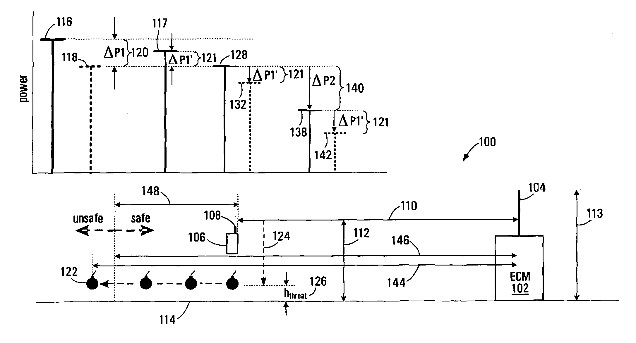
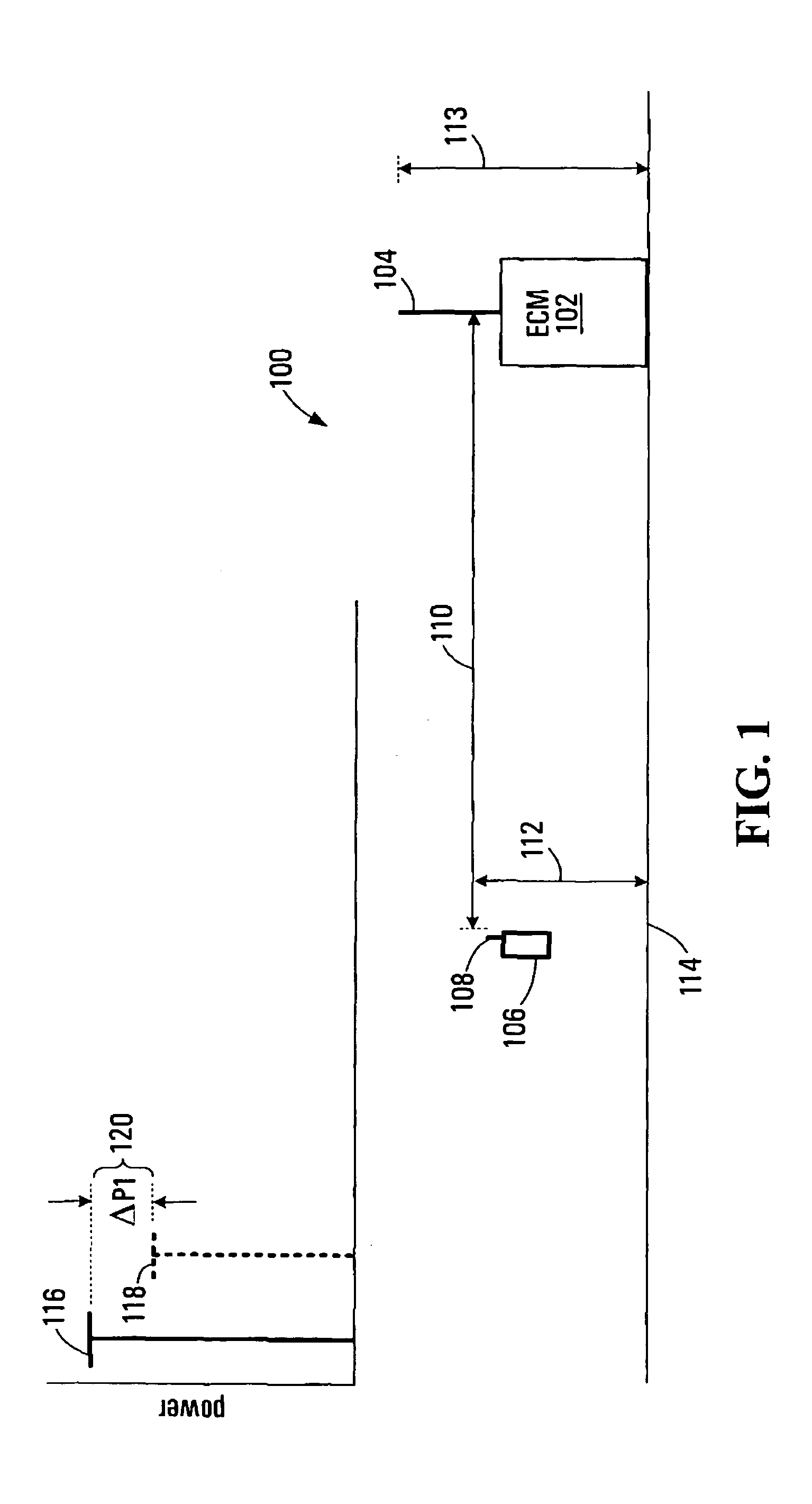
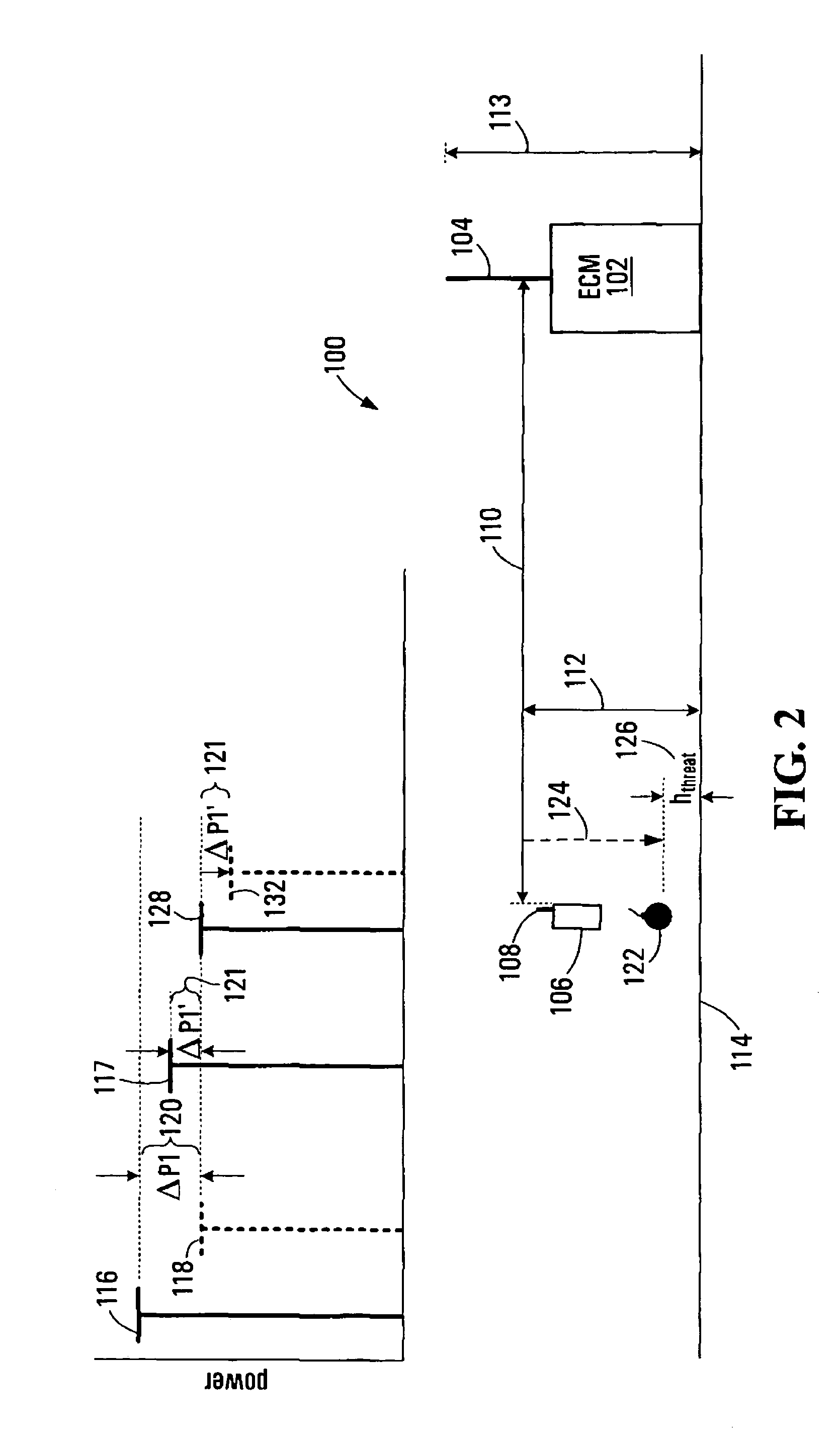
[0097]Various devices and methods for predicting the effectiveness of an ECM system in an area around the ECM system are provided. Some embodiments of the methods and devices provide estimation of the protection range of an ECM system in-situ and in real or near-real time. The devices could be implemented as stand-alone units, or as new feature integrated into new or existing equipment. Embodiments of the present invention are not limited to ECM applications. More generally, some embodiments of the present invention provide an estimation of a range at which a Measure of Merit (MoM) is satisfied. For example, for ECM applications, the protection range may be defined by the range at which a probability of preventing triggering of a threat device drops below a threshold value. In other non-ECM implementations, the MoM may simply be the range at which received RF power, from an RF transmitter drops below a threshold value.

[0098]In some embodiments, the devices and methods determine if t...


PUM


Abstract

A device and method for estimating the operational effectiveness, status, and protection range of an electronic countermeasures system in real time or near real time are provided. The device and method calculate a predicted ECM power at a given location using a propagation and scenario model. Then a measured ECM power at the given location is used to determine a correction value equal to the difference between the calculated and measured ECM powers. The correction value and the propagation model are then used with a heuristic method to refine estimates of propagation and scenario parameters. The refined parameter set is used to produce a refined prediction of ECM power, which is used to create a refined correction factor. The refined correction factor is used to determine predicted ECM powers at a plurality of locations in an area around the device to determine a boundary of protection.

Description

RELATED APPLICATION[0001]This application claims the benefit of prior U.S. provisional application No. 60 / 917,368 filed May 11, 2007, which is hereby incorporated by reference in its entirety.FIELD OF THE PRESENT INVENTION[0002]The present invention pertains to the field of radio frequency signalling and electronic countermeasures.BACKGROUND OF THE PRESENT INVENTION[0003]Electronic countermeasures (ECM) are a subsection of electronic warfare which includes any sort of electrical or electronic device designed to prevent or disrupt electromagnetic signalling. It may be used both offensively and defensively. ECM often takes the form of jamming, whereby a jamming signal is transmitted by an ECM system to block the reception of other signals within the bandwidth of the jamming signal. However, in general the jamming signal has a finite physical area of effect determined by the area distribution of its radiated energy. Outside this area the jamming may be only partially effective.[0004]So...

Claims


Application Information

Patent Timeline
Patent Type & Authority Patents(United States)
IPC IPC(8): H01Q15/00
CPCF41H13/0075H04K3/43H04B17/3913H04K3/94H04B17/327H04K3/42H04K2203/24H04K3/92G01S7/02G01S7/36G01S7/38G01S7/40G01S13/00G01S13/78
Inventor CHARLAND, SHAWN
Owner SKY IND
Learn More