Ignition method with stop switch for internal-combustion engines

a technology of internal combustion engine and stop switch, which is applied in the direction of engine ignition, contacts, other installations, etc., can solve the problems of incomplete failure no longer starting for a long time, and erroneous operation of internal combustion engine, so as to prevent ignition, prevent ignition, and prevent ignition

Active Publication Date: 2007-01-02
PRUFREX ELECTRO APPBAU INH HELGA MULLER GEBR DUTSCHKE
View PDF6 Cites 14 Cited by
  • Summary
  • Abstract
  • Description
  • Claims
  • Application Information

AI Technical Summary

Benefits of technology

[0019]For stopping the motor, there is a stop switch element, a stop switch, or a stop button, with which the triggering of the ignition is prevented or can be prevented. Such a stop switch element preferably has the effect that the alternating charging voltage or at least a relevant part of the alternating charging voltage, which is used especially for charging the energy element, is short-circuited to ground either directly or via one or more switching elements, such as thyristors. Alternatively, the ignition voltage can also be grounded with or without the intermediate connection of other switching elements.
[0024]In a preferred embodiment of the method, the prevention of the ignition by means of the stop switch element is realized by hardware devices, preferably independent of the controller. Preferably, the stop switch element directly short-circuits the charging voltage and / or ignition voltage, or prevents the charging voltage and / or ignition voltage, in particular, from being applied to the switch contacts of the stop switch element by, for instance, switching them to ground. This embodiment can exhibit the advantage that self-cleaning effects occur on the STOP switch element through the short-circuiting of high charging voltages. A configuration of the invention wherein there is no direct signal path leading from the stop switch (STOP) to the controller (MC, U8), especially a microprocessor, corresponds to this embodiment. Thus, without the interaction of the microprocessor or controller, the stop switch, especially the stop switch element, can intervene in elements of the high-current or power part of the ignition system according to the invention for suppressing the ignition spark.
[0025]In an advantageous refinement of the method, an OFF value is allocated to the stop flag or the other state variables when the stop switch element is activated and an ON value is allocated to the stop flag before or at restart of the machine or its run-down. The set OFF value has the effect that an operating state of the ignition system is assumed, especially one controlled by the controller, in which no ignition spark is generated or discharged. The set ON value has the effect that an operating state of the ignition system, especially one controlled by the controller, is assumed in which ignition sparks are generated and / or discharged. Thus, the prevention of the triggering of the ignition can be implemented both directly by the stop switch element and also by the controller. In particular, the prevention of ignition is caused first by the switching of the stop switch element and is then continued and / or performed parallel in time by the controller. Thus, preferably a stop button method is performed, wherein, through a short activation of the stop switch element, especially the stop button, the motor is turned off until stopped, wherein flag information on the stop button activation is stored, for example, in the form of an OFF value, and before restart, it is reset to an ON value.
[0032]In one refinement of the device, the information on the OFF operating state is not stored in a single bit, but instead it is coded and / or stored as a pattern in several bits or bytes and thus a redundant information pattern and / or an error-correcting code is used. Because the turning off of a motor concerns a safety function, through this refinement, an improvement of the behavior in terms of electromagnetic compatibility (EMV) can be achieved.
[0049]In one advantageous refinement of the magnetic ignition module, the controller is constructed in terms of circuitry and / or programming especially such that the stop flag is set from an OFF value to an ON value due to the initialization of the controller, caused by a POWER ON RESET. In this design, the stop flag is held in a defined manner at the OFF value until the supply voltage of the controller has fallen below the minimum voltage for powering the read / write / working memory (RAM). Preferably, the magnetic ignition module is constructed such that in this state, either the charging voltage is too low to generate an ignition spark and / or the controller has a LOW VOLTAGE RESET function, which has the effect that no trigger pulse is output to activate the ignition switch and / or the triggering of the ignition is prevented, thus blocked. When the low-power motor is restarted, through the increase of the supply voltage, the POWER ON RESET function is activated, which sets the stop flag to the ON value for subsequent initialization of the controller. Preferably, a discharge path can be provided for a storage capacitor, which guarantees the supply voltage of the controller, in order to narrow the total time tolerance for reaching the LOW VOLTAGE RESET state in a defined way.
[0054]The restart of the internal-combustion engine is simplified and accelerated and, in particular, it is possible immediately after and / or even during the motor run-down. For the stop switch, previously common standard configurations can be used, which can also be exposed to current contact loads with self-cleaning effects, in that they are used for short-circuiting the same signals as in the state of the art. Additional hardware expense is eliminated (cost advantage). Because the stop switch function according to the invention can be realized essentially by means of software, ignition control hardware known, for example, from DE 102 02 422 can be reused with essentially no changes. The adaptation to the single added stop switch can be realized substantially by changing the internal (program) flow in the switching equipment.

Problems solved by technology

A known problem in the start and stop phase, which can grow to a temporary complete failure of the internal-combustion engine, is the erroneous operation of the internal-combustion engine in a restart, i.e., starting immediately after the internal-combustion engine is stopped.
Now, if the user forgets, before the restart, to deactivate the stop switch, this leads to “flooding” of the internal-combustion engine, so that it can no longer be started for a long time.
Thus, a disadvantage in the proposed device is that immediate restart of the engine after stoppage is not possible, which means a waiting period for the operator.

Method used


Image

  • Ignition method with stop switch for internal-combustion engines
  • Ignition method with stop switch for internal-combustion engines
  • Ignition method with stop switch for internal-combustion engines

Examples


Embodiment Construction

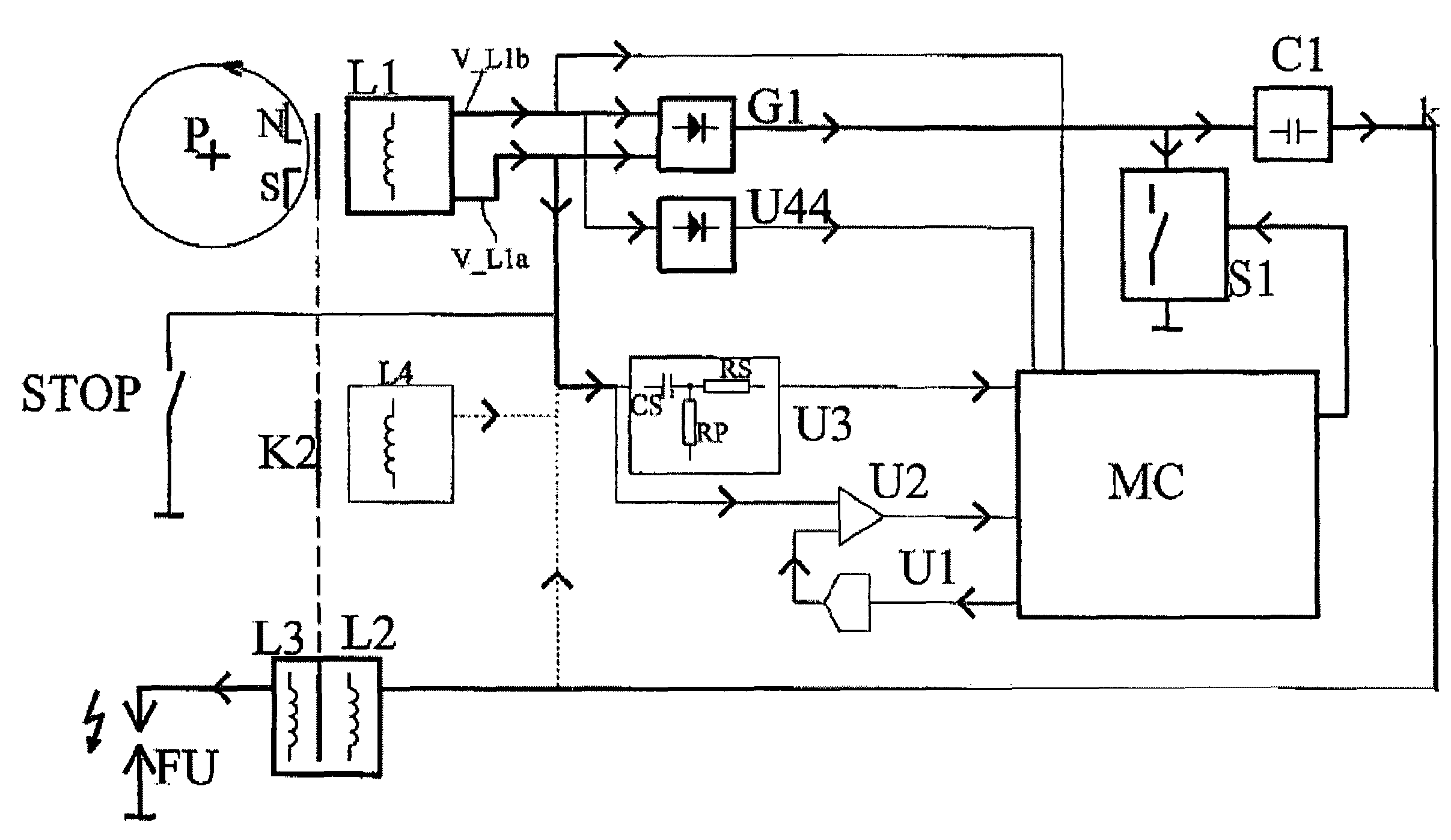
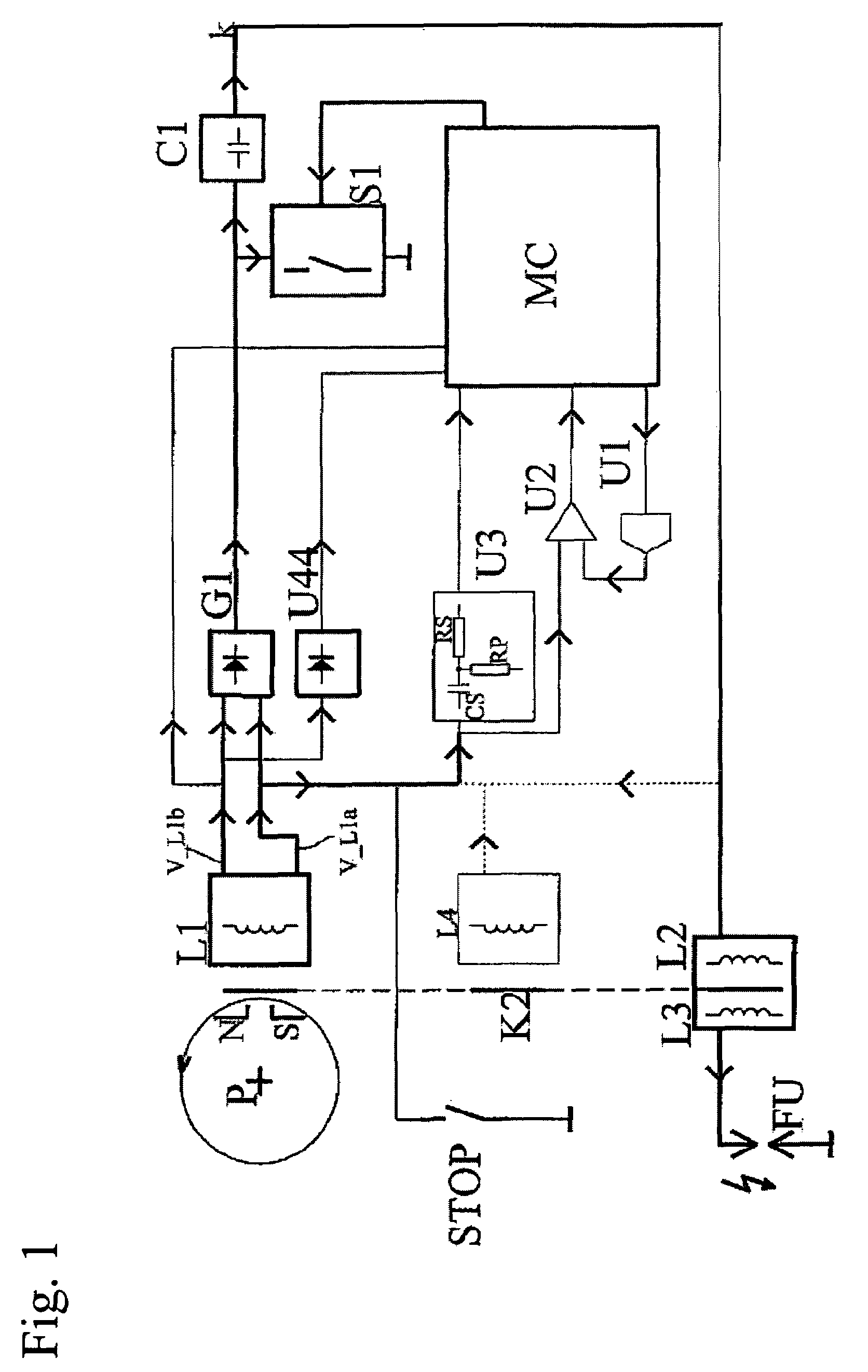
[0060]The block diagram in FIG. 1 is described up to the stop switch STOP in DE 102 01 422 A1, whose contents of disclosure are incorporated entirely in the present application by means of reference.

[0061]In a schematic representation, FIG. 1 shows a magnet wheel P with permanent magnets N, S in the top left region. During the operation of a motor, not shown, the magnet wheel rotates and induces a charging voltage V_L1 in a charging coil L1. The charging voltage is led via a bridge rectifier G1 to an ignition capacitor C1. The ignition capacitor C1 is used for storing ignition energy for generating an ignition spark and is charged up to a capacitor voltage.

[0062]The ignition capacitor C1 is discharged by closing a switch element S1, which is controlled by a programmable, electronic controller MC, for example, a microcontroller. After the switch element is closed, the ignition capacitor is discharged via a primary coil L2 of an ignition transformer L3, L2. Due to a winding ratio of t...


PUM


Abstract

For stopping an internal combustion engine, a stop switch prevents the triggering of the ignition. A controller in the ignition circuit determines the state of the stop switch by evaluating signals on the state of the internal combustion engine, corresponding information data is generated, and a corresponding stop flag is set and / or enabled. Depending on this information, the activation of the ignition switch, that controls ignition spark, is either blocked or enabled by the controller.

Description

CROSS-REFERENCES TO RELATED APPLICATIONS[0001]This application claims the benefit of Foreign Applications EP 04 019 782.4, filed Aug. 20, 2004 and DE 10 2004 059 070.2, filed Dec. 7, 2004.(b) CROSS-REFERENCES TO RELATED APPLICATIONS[0002]This application claims the benefit of Foreign Applications EP 04 019 782.4, filed Aug. 20, 2004 and DE 10 2004 059 070.2, filed Dec. 7, 2004.(c) STATEMENT REGARDING FEDERALLY-SPONSORED RESEARCH AND DEVELOPMENT[0003](Not Applicable)(d) REFERENCE TO AN APPENDIX[0004](Not Applicable)BACKGROUND OF THE INVENTION[0005]1. Field of the Invention[0006]The invention relates to an ignition method for internal-combustion engines, a magnetic ignition module, and also an arrangement for performing the ignition method.[0007]2. Description of the Related Art[0008]In the operation of internal-combustion engines, especially low-power engines, high demands are placed on the efficiency of the ignition systems, so that existing exhaust and noise emission guidelines, as...

Claims


Application Information

Patent Timeline
Patent Type & Authority Patents(United States)
IPC IPC(8): F02P5/00F02P3/06
CPCF02P9/002F02N11/0803F02N11/10F02P1/086H01H1/605F02P5/1502F02P11/025F02P3/0807
Inventor KIESSLING, LEO
Owner PRUFREX ELECTRO APPBAU INH HELGA MULLER GEBR DUTSCHKE
Why Eureka
Try Eureka