Radiation phase contrast imaging apparatus

a technology of contrast imaging and phase image, which is applied in the direction of material analysis using wave/particle radiation, instruments, nuclear engineering, etc., can solve the problems of difficult manufacturing such multi-slit units and unfavorable phase images, and achieve the effect of reducing the cost of the apparatus

Inactive Publication Date: 2012-05-22
FUJIFILM CORP
View PDF4 Cites 50 Cited by
  • Summary
  • Abstract
  • Description
  • Claims
  • Application Information

AI Technical Summary

Benefits of technology

[0031]Further, when an electron beam emission control unit is further provided for independently controlling the emission of electron beam from each of the plurality of electron sources to the target, the focus interval of the radiation may be changed / set such that a grating image formed by radiation from each focus by way of the first grating is substantially superimposed with the structure of the second grating by controlling, after installing the radiation sources, first grating, and second grating, the emission of electron beam emitted from each electron source to the target. This allows a radiation phase contrast imaging apparatus to be configured without requiring highly precise gratings and geometrical arrangement of each optical element.
[0032]Still further, when a gate electrode that restricts the passage of the electron beam is provided between the electron sources and the target and the emission of the electron beam to the target is controlled by switching a voltage applied to the gate electrode by the electron beam emission control unit, or the emission of the electron beam to the target is controlled by controlling a potential difference between an extraction electrode, which is provided between the electron sources and the target, and each electron source by the electron beam emission control unit, the focus position of radiation may be changed by a simple structure.
[0034]According to the second radiation phase contrast imaging apparatus of the present invention, a plurality of electron sources, each for emitting an electron beam, is provided, then the grating and the periodic information imaging radiation image detector are disposed in an optical axis direction of the radiation so as to be able to substantially superimpose each image of the grating formed based on radiation corresponding to each electron source on a surface of the periodic information imaging radiation image detector, and each phase image of the same subject is formed inside of the periodic information imaging radiation image detector by the radiation corresponding to each electron source by way of the grating and linear electrodes of the periodic information imaging radiation image detector. This allows a radiation phase contrast imaging apparatus to be formed without using a multi-slit unit, as in the first radiation phase contrast imaging apparatus of the present invention. Further, the use of the periodic information imaging radiation image detector allows the apparatus to be formed with only one grating, whereby the cost of the apparatus may be reduced.

Problems solved by technology

Thus, the method poses a problem that a favorable phase image can not be obtained due to mechanical instability, body movement of the subject, or the like during the exposure period for detecting a subtle variation of the wavefront.
Consequently, it is necessary to form a very small slit using a member having a low X-ray transmittance, and it has been very difficult to manufacture such multi-slit units.

Method used


Image

  • Radiation phase contrast imaging apparatus
  • Radiation phase contrast imaging apparatus
  • Radiation phase contrast imaging apparatus

Examples


first embodiment

[0109]Further, in the radiation phase contrast imaging apparatus an electron beam emitted from electron source 15a is controlled by electron beam emission control unit 16 by selectively switching the high voltage applied between extraction electrode 15c and target 15b, thereby controlling the focus interval of the radiation but, for example, the interval between each electron beam emitted from each electron source 15a may be controlled by controlling the electric field formed by electrostatic lens 15d and whereby focus interval of radiation may be controlled.

[0110]Still further, in radiation sources 1a of the first embodiment, emission of electron beam emitted from each electron source 15a onto each target 15b may be controlled by further providing gate electrode 15e between each electron source 15a and each target 15b as shown in FIG. 9, then applying a negative voltage to gate electrode 15e, and controlling the magnitude of the negative voltage. More specifically, the emission of...

second embodiment

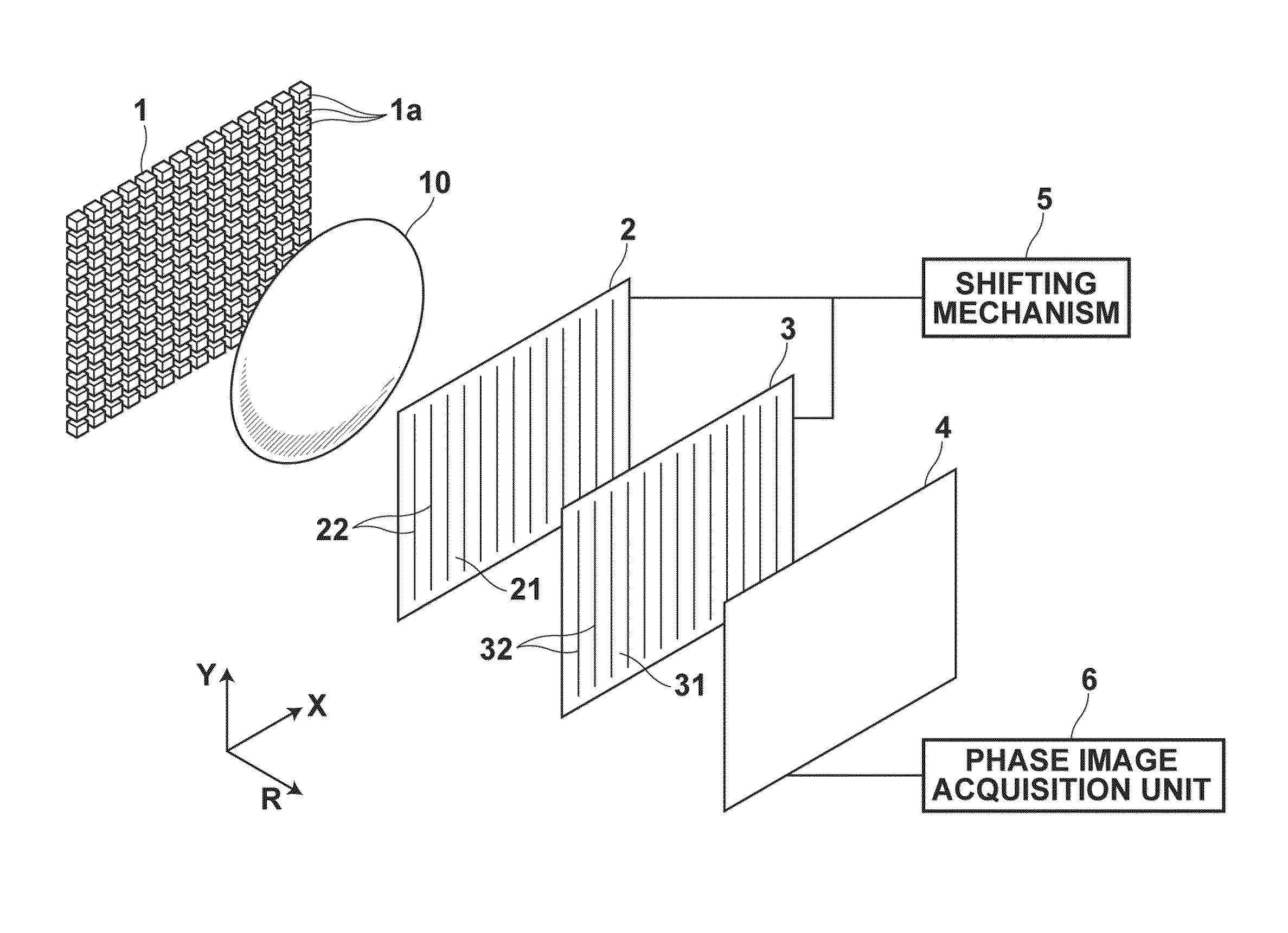
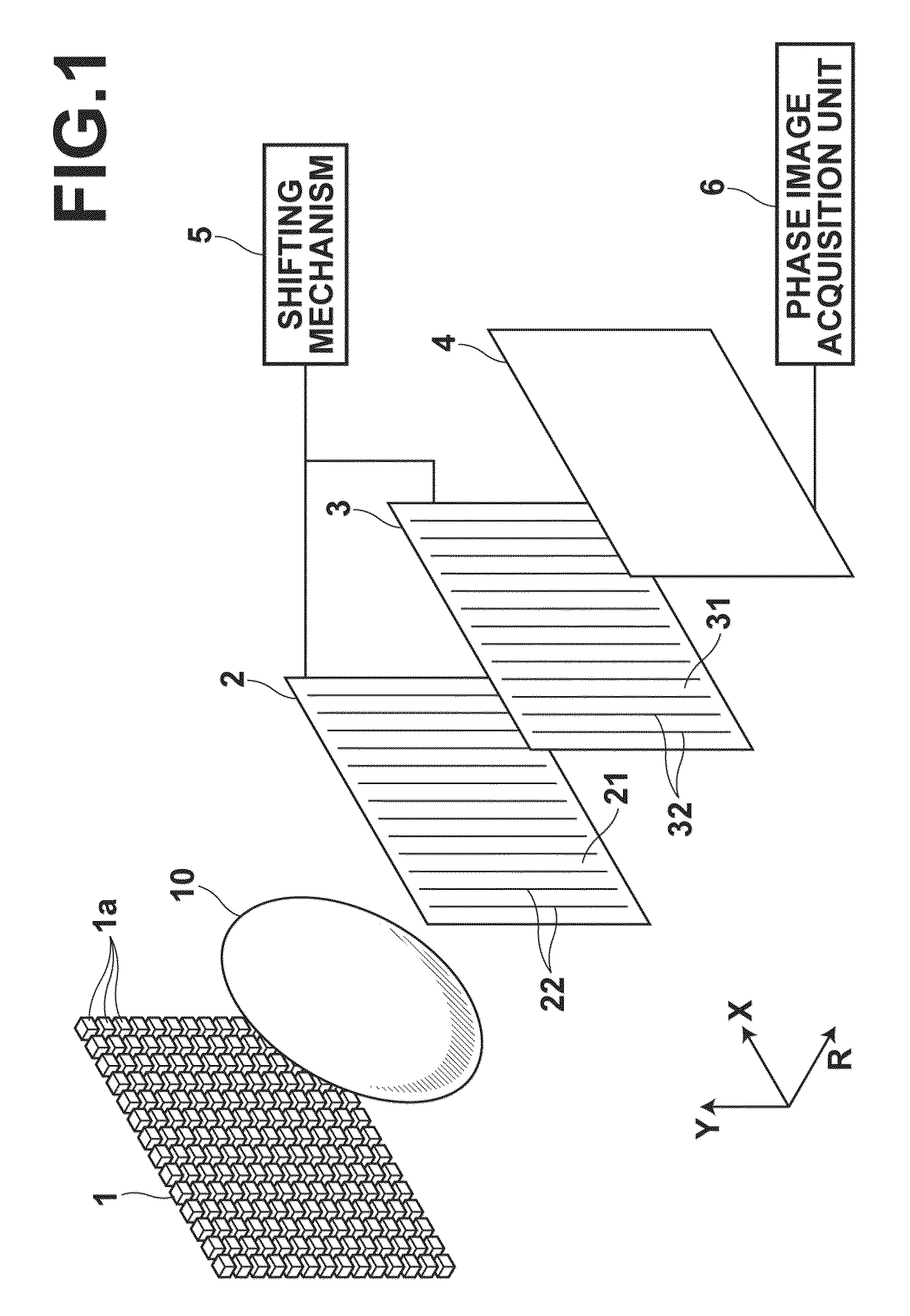
[0115]As illustrated in FIG. 10, the radiation phase contrast imaging apparatus includes radiation emission unit 1 that emits radiation onto subject 10, grating 20 for receiving the radiation transmitted through subject 10 and diffracting the radiation, periodic information imaging radiation image detector 40 for detecting periodic information of the radiation diffracted by grating 20, shifting mechanism 55 for shifting grating 20 and periodic information imaging radiation image detector 40 in a direction orthogonal to linear electrodes of detector 40 (X direction in FIG. 10) along the respective planes, and phase image acquisition unit 6 for forming a phase image based on an image signal detected by periodic information imaging radiation image detector 40.

[0116]Radiation emission unit 1 has an identical structure to that of the first embodiment.

[0117]Grating 20 has an identical structure to that of the first grating in the radiation phase contrast imaging apparatus according to th...

third embodiment

[0178]As illustrated in FIGS. 26A to 26C, periodic information imaging radiation image detector 200 of the radiation phase contrast imaging apparatus includes the following stacked in the order listed below: first electrode layer 201 that transmits radiation; recording photoconductive layer 202 that generates charges by receiving radiation transmitted through first electrode layer 201; charge transport layer 204 that acts as an insulator against charges of one polarity of those generated in recording photoconductive layer 202 and as a conductor for charges of the other polarity; readout photoconductive layer 205 that generates charges by receiving readout light; and second electrode layer 206. Storage section 203 for storing charges generated in recording photoconductive layer 202 is formed adjacent to the interface between recording photoconductive layer 202 and charge transport layer 204. Each of the layers described above is stacked on glass substrate 207 one after another from ...


PUM

PropertyMeasurementUnit
refractive index distributionaaaaaaaaaa
thicknessaaaaaaaaaa
widthaaaaaaaaaa

Abstract

A radiation phase contrast imaging apparatus, including a radiation emission unit having a plurality of electron sources for emitting electron beams, and a target for emitting radiation through collision of electron beam emitted from each electron source, a first grating in which grating structures for diffracting radiation are disposed periodically, a second grating in which grating structures for transmitting and shielding radiation are disposed periodically, and a radiation image detector for detecting radiation transmitted through the second grating, in which the first and second gratings are disposed in an optical axis direction of the radiation so as to be able to substantially superimpose each image of the first grating formed based on radiation corresponding to each electron source on a surface of the second grating, and the radiation corresponding to each electron source forms each phase image of the same subject on the radiation image detector.

Description

BACKGROUND OF THE INVENTION[0001]1. Field of the Invention[0002]The present invention relates to a radiation phase contrast imaging apparatus using a grating.[0003]2. Description of the Related Art[0004]A method for detecting a variation of wavefront arising from a difference in refractive index of media in a transmission path of an X-ray incident on a subject using an X-ray Talbot interferometer to generate an image of the subject is proposed as described, for example, in U.S. Pat. No. 7,180,979.[0005]The method described above has a potentiality to utilize a corn beam X-ray source or the like, as opposed to other phase imaging methods that uses a crystal analysis body which basically requires parallel monochrome X-rays.[0006]The method using a Talbot interferometer uses, for example, a microfocus X-ray source because it requires a high degree of spatial coherence. Such an X-ray source can yield quite a small amount of X-rays in a short exposure time of several seconds, so it neces...

Claims


Application Information

Patent Timeline
Patent Type & Authority Patents(United States)
IPC IPC(8): G01N23/04
CPCG01N23/20075A61B6/484G01N2223/203G01N23/041
Inventor MURAKOSHI, DAITAKAHASHI, KENJI
Owner FUJIFILM CORP
Why Eureka
Try Eureka