Method of determining a speed of rotation of an axially symmetrical vibrating sensor, and a corresponding inertial device

a technology of axial symmetry and vibrating sensor, which is applied in the direction of instruments, devices using electric/magnetic means, acceleration measurement using interia forces, etc., can solve the problems of not only function, drift error, and drift error, and achieve the effect of minimizing drift error

Active Publication Date: 2012-05-29
SAFRAN ELECTRONICS & DEFENSE
View PDF5 Cites 5 Cited by
  • Summary
  • Abstract
  • Description
  • Claims
  • Application Information

AI Technical Summary

Benefits of technology

[0008]An object of the invention is to determine the speed of rotation of an axially symmetrical vibrating sensor by minimizing drift error.SUMMARY OF THE INVENTION
[0012]Considering several evaluations each performed in a different position of the vibration enables to reduce or eliminate the error generated by the harmonic drift.
[0021]This eliminates the effect of the harmonic of order n. For two vibration positions offset by π / n, the harmonic of order n has amplitudes of the same absolute value but of opposite sign, such that by taking the mean of the evaluations in two positions that are symmetrically offset by π / n, the modal offset is π, such that the amplitudes of the error due to the harmonic of order n cancel.
[0031]using two positions θ0 and θ2=θ0+90° permits to eliminate the harmonics of orders 2, 6, 10, 14, 18 and 20,
[0033]using four positions θ0, θ1=θ0+45°, θ2=θ0+90°, and θ3=θ0+135°, permits to eliminate the harmonics of orders 2, 4, 6, 10, 12, 14, 18, 20.

Problems solved by technology

It is also known that vibrating gyros present a drift error that is manifested when the gyro is operating in free gyro mode by variation in the position of the vibration even when the carrier is not subject to any rotation.
Nevertheless, drift error is not only a function of the position of the vibration, but also a function of ambient temperature and of the aging of the gyro.
In practice, possibilities for correction are therefore limited.

Method used


Image

  • Method of determining a speed of rotation of an axially symmetrical vibrating sensor, and a corresponding inertial device
  • Method of determining a speed of rotation of an axially symmetrical vibrating sensor, and a corresponding inertial device
  • Method of determining a speed of rotation of an axially symmetrical vibrating sensor, and a corresponding inertial device

Examples


Embodiment Construction

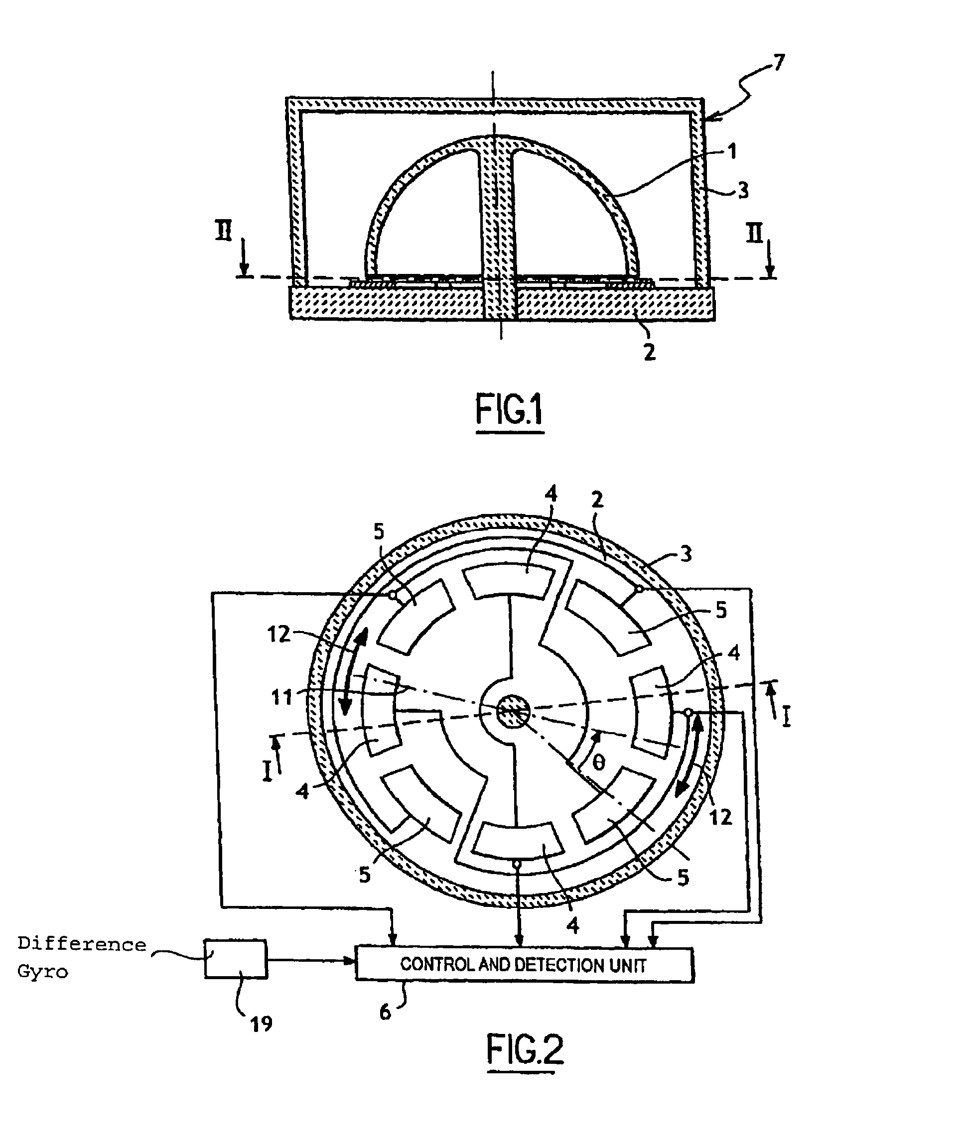
[0049]With reference to FIGS. 1 and 2, the inertial device of the invention is illustrated as a vibrating sensor with an elastic line of order 2. The device comprises a hemispherical bell vibrating sensor 7 comprising in conventional manner a silica bell 1 mounted on a base 2 likewise made of silica, the bell 1 being surrounded by a sealed housing 3 enabling the sensor to be put under a vacuum.

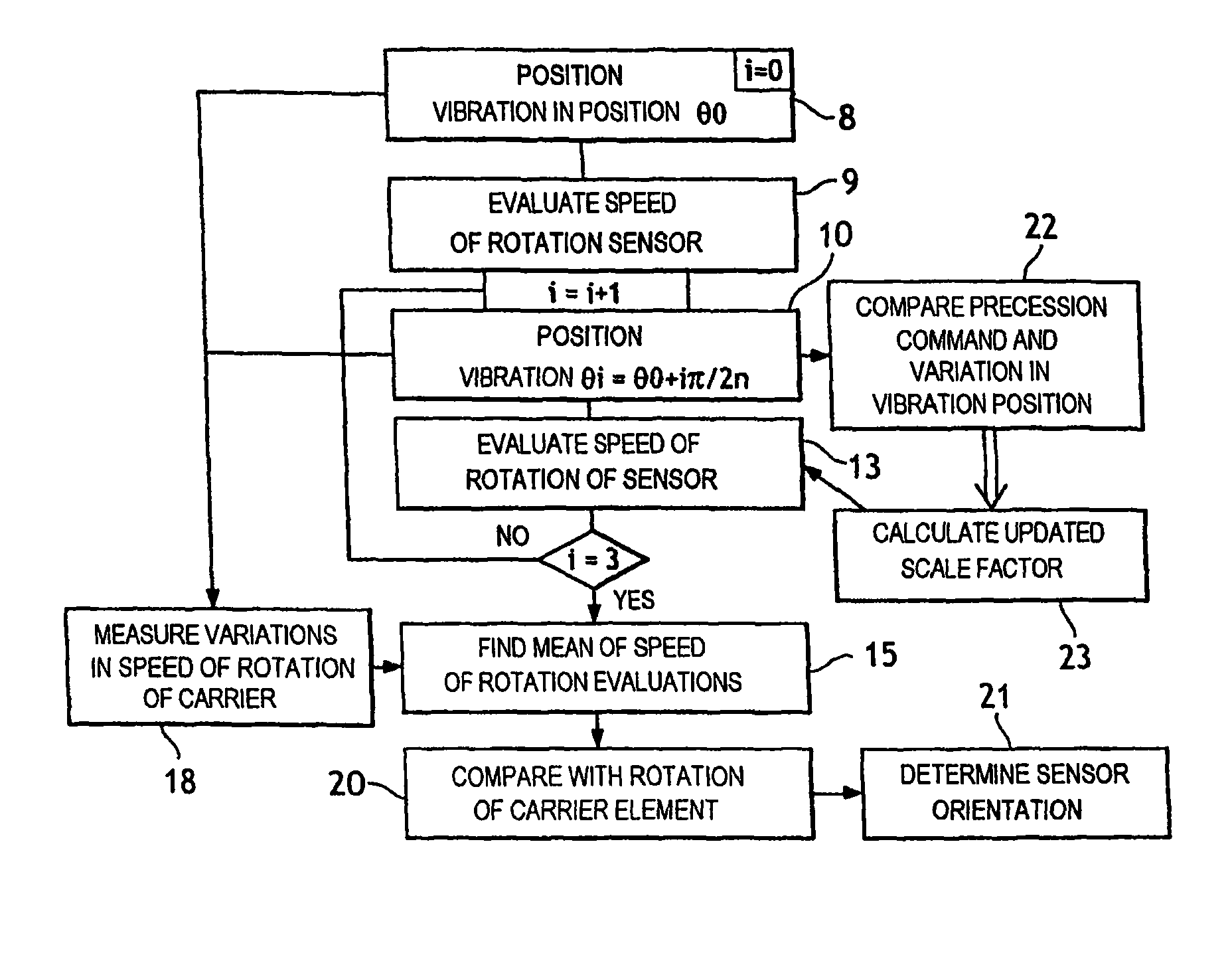
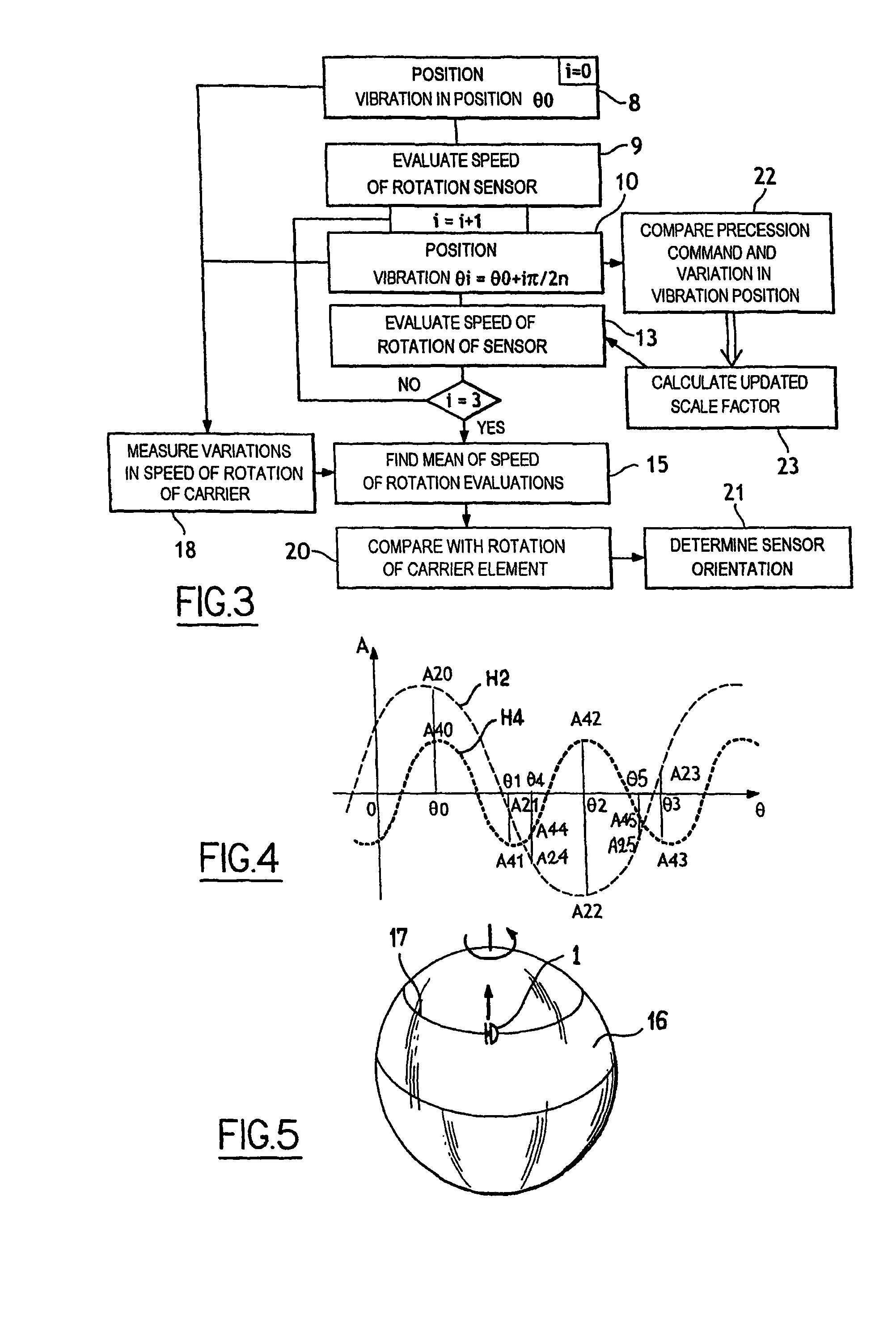
[0050]Also in conventional manner, the inside surface of the bell 1 is metallized as is its bottom edge, and the bottom edge extends facing two pairs of control electrodes 4 and two pairs of detection electrodes 5 that are suitably connected to a control and detection unit 6 for generating vibration 11 represented by a chain-dotted line in FIG. 2 and of position that is identified by an angle θ relative to a reference electrode 5. The position of the vibration 11 is controlled by the control unit 6 applying precession command to the control electrodes 4.

[0051]Two implementations of the method ...


PUM


Abstract

A method and device of determining a speed of rotation of an axially symmetrical vibrating sensor. The sensor has a vibrating member associated with control electrodes and with detection electrodes for generating a vibration presenting an elastic line possessing periodicity of order n and having a position that is variable as a function of the rotation of the sensor. The method includes performing successive evaluations of the speed for a predetermined number of positions of the vibration relative to the electrodes. The positions are geometrically offset relative to each other and the vibration is moved from one position to another by applying a precession command using a pre-established scale factor. The method also includes determining a speed of rotation in function of the evaluations.

Description

CROSS REFERENCE TO RELATED APPLICATIONS[0001]This application is a Continuation-in-Part of co-pending application Ser. No. 11 / 898,495, filed on Sep. 12, 2007, and for which priority is claimed under 35 U.S.C. §120; the entire contents of which are hereby incorporated by reference.[0002]The present invention relates to a method of determining a speed of rotation of an axially symmetrical vibrating sensor, and to a corresponding inertial device including an axially symmetrical vibrating sensor. The invention more precisely concerns sensors presenting an angular drift of the position of the vibration, sais angular drift harmonically depending on the position of said vibration relative to the casing of the device.BACKGROUND OF THE INVENTION[0003]In order to determine the orientation of a carrier, in particular in order to navigate an airplane, it is known that an inertial device can be used that comprises one or more axially symmetrical vibrating sensors, each making use of a resonator ...

Claims


Application Information

Patent Timeline
Patent Type & Authority Patents(United States)
IPC IPC(8): G01P3/44
CPCG01C19/5691
Inventor CARON, JEAN-MICHELROBERFROID, DAVID
Owner SAFRAN ELECTRONICS & DEFENSE
Why Eureka
Try Eureka