Fatigue resistant transverse lubrication passage for transmission shafts

a transverse lubrication and transmission shaft technology, applied in the field of transmissions, can solve the problems of fatigue failure, failure of the outer surface of the rotating shaft near the radial lubrication passage, and the increasing performance demands of the transmission, so as to reduce the stress produced around the hole by the torque transmitted through the rotating shaft, the effect of high torque and low cos

Inactive Publication Date: 2012-05-29
FORD GLOBAL TECH LLC
View PDF11 Cites 5 Cited by
  • Summary
  • Abstract
  • Description
  • Claims
  • Application Information

AI Technical Summary

Benefits of technology

[0008]Any cross section taken along the entire length of the radial passage in the first preferred embodiment is preferably the same shape and size as any other cross section taken along the length of the radial passage. In other words the size and shape of the radial passage is the same along its length. However, in a second preferred embodiment of the invention, the radial lubrication passage varies in size and shape along the transverse axis. More specifically cross sections of the outer portion of the radial passage taken sequentially along the transverse axis are elongated near the outer peripheral surface of the shaft but become circular near the central axis thus forming a tapered surface along the outer portion of the radial passage while the remainder of the passage located near the central axis is formed with a cylindrical surface. It is particularly advantageous to incorporate the lubrication system in bidirectional rotating shafts that transmit relatively high levels of torque in one direction more than an opposing direction such that the high torque is only experienced unidirectionally. With this arrangement, stress produced around the hole by torque transmitted through the rotating shaft is minimized, thus reducing fatigue and increasing a useful life of the transmission.

Problems solved by technology

While such designs have proven satisfactory in the past, the performance demands on transmissions have been increasing over time.
In the case of a planetary transmission fatigue, failures can occur at the outer surfaces of the rotating shafts near the radial lubrication passages.
Such fatigue failures are particularly problematic on rotating shafts that are subject to heavy loads.
Furthermore the cost of using more durable materials is significant.
In either case the additional cost is unacceptable.

Method used


Image

  • Fatigue resistant transverse lubrication passage for transmission shafts
  • Fatigue resistant transverse lubrication passage for transmission shafts
  • Fatigue resistant transverse lubrication passage for transmission shafts

Examples


Embodiment Construction

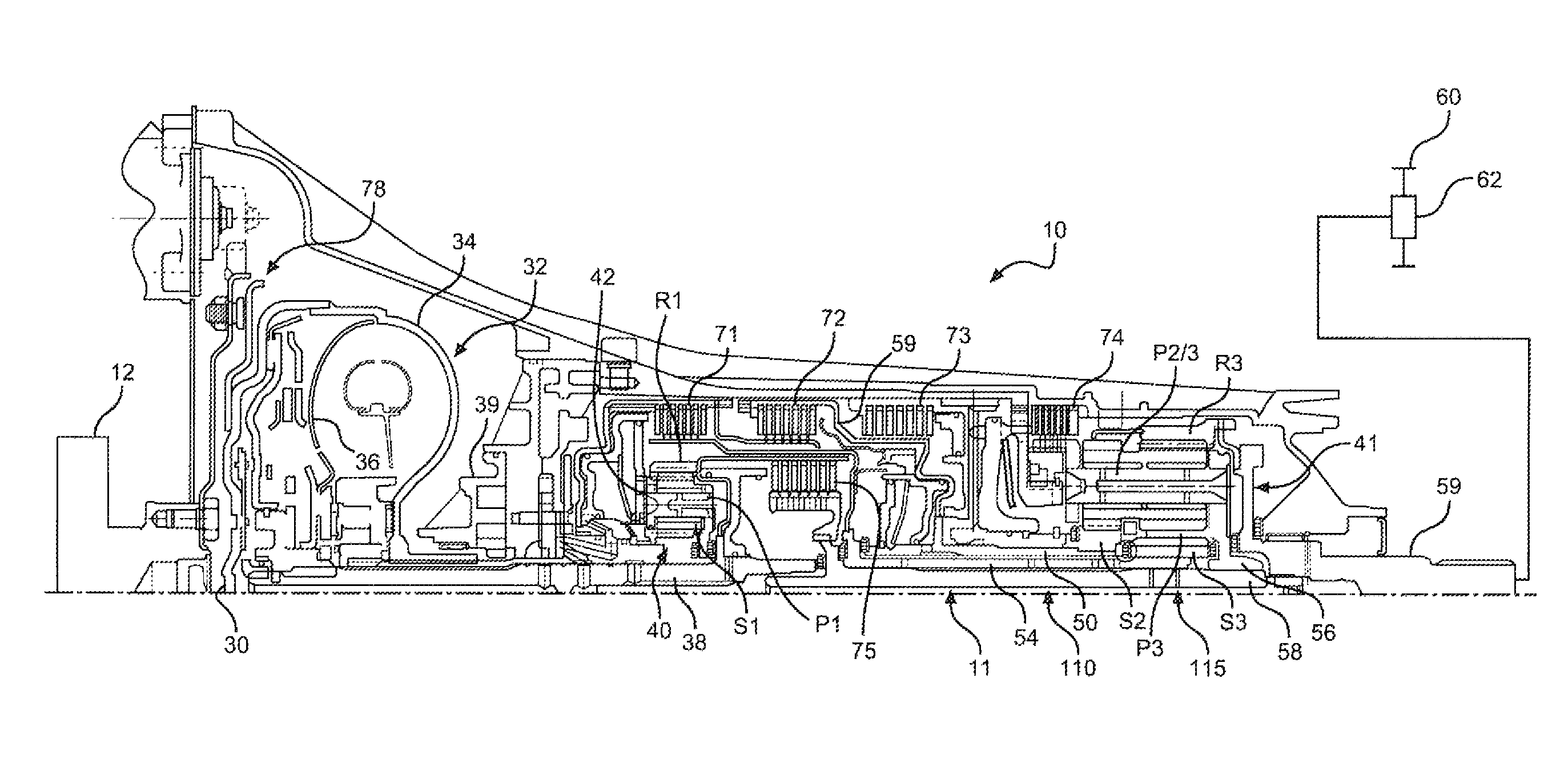
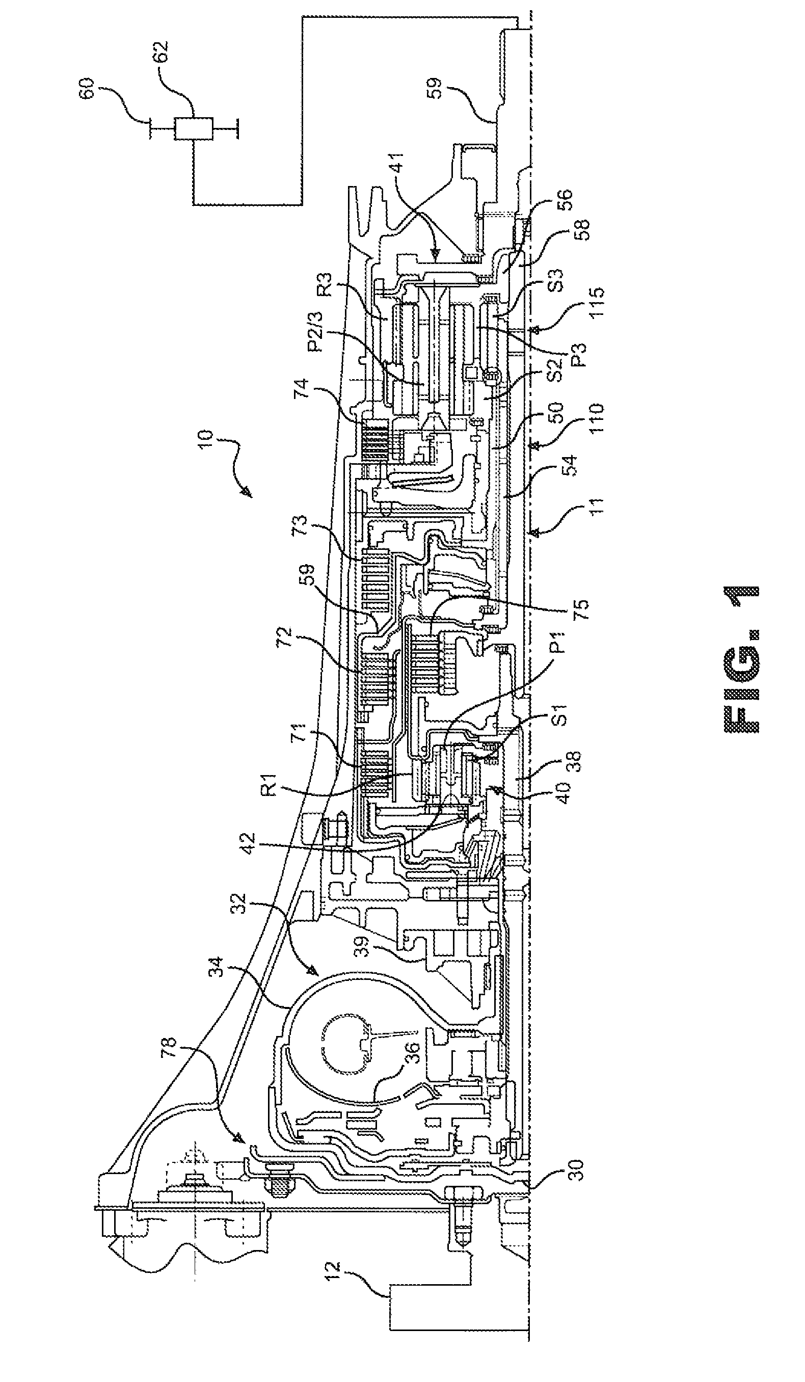
[0018]With initial reference to FIG. 1, a planetary transmission 10 incorporating a lubrication system 11 is schematically illustrated. Torque from an engine 12 is distributed to torque input element 30 of hydrokinetic torque converter 32. An impeller 34 of torque converter 32 develops turbine torque on a turbine 36 in a known fashion. Turbine torque is distributed to a turbine shaft, which also constitutes a transmission input shaft 38. Impeller 34 is connected to a relatively small oil pump assembly 39.

[0019]In the exemplary embodiment shown, transmission 10 of FIG. 1 includes a simple planetary gearset 40, a compound planetary gearset 41 and numerous rotating shafts, which contain parts of lubrication system 11. Gearset 40 has a permanently fixed sun gear S1, a ring gear R1 and planetary pinions P1 rotatably supported on a carrier 42. Transmission input shaft 38 is drivably connected to ring gear R1. Compound planetary gearset 41, sometimes referred to as a Ravagineaux gearset, h...


PUM

PropertyMeasurementUnit
stressaaaaaaaaaa
oval shapeaaaaaaaaaa
torqueaaaaaaaaaa

Abstract

A lubrication system for transporting lubrication oil in an automatic transmission includes a radial lubrication passage opening at a hole in an outer peripheral surface of a shaft. The hole has a cross section that is elongated only along a first axis offset from a central axis the shaft so as to follow angular deformation caused by unidirectional torque applied to the shaft whereby stress produced around the hole by torque transmitted through the rotating shaft is reduced, thus minimizing fatigue and increasing a useful life of the automatic planetary transmission. Preferably cross sections of the radial passage taken sequentially along the transverse axis are elongated near outer peripheral surface of the shaft but become circular towards the central axis. With this arrangement stress produced around the hole by torque transmitted through the rotating shaft is reduced thus reducing fatigue and increasing a useful life of the transmission.

Description

FIELD OF THE INVENTION[0001]The present invention pertains to the art of transmissions, particularly providing shafts with lubricating passages for distributing lubricating oil to various moving parts in an automatic transmission. Furthermore, the invention pertains to ensuring that the transmission shafts are still resistant to fatigue after the lubricating passages have been formed.BACKGROUND OF INVENTION[0002]Automatic vehicle transmissions function to transmit torque from an input shaft connected a power source, such as an internal combustion engine or an electric motor, to an output shaft connected to a set of driven wheels. Typically the transmission is provided with a gearing system that includes interlocking gears mounted on rotating shafts designed to vary a ratio of the speed of the input shaft to the speed of the output shaft. In order to increase the efficiency of the gearing system, the system needs to be lubricated.[0003]In addressing this problem it is known to establ...

Claims


Application Information

Patent Timeline
Patent Type & Authority Patents(United States)
IPC IPC(8): F16H57/04
CPCF16C3/02F16H57/043Y10T29/49826F16H57/0484
Inventor DEUTSCH, LAURENCE ANDREWTHOMAS, STEVEN GERALD
Owner FORD GLOBAL TECH LLC
Why Eureka
Try Eureka