
Reduced-pressure, linear wound closing bolsters and systems

a wound closure and linear technology, applied in the field of medical treatment systems, can solve the problems of high stress, inability to reduce and inability to so as to reduce the time for wound strength and reduce the scar formation at the wound

Active Publication Date: 2012-05-29
3M INNOVATIVE PROPERTIES CO
View PDF264 Cites 92 Cited by
  • Summary
  • Abstract
  • Description
  • Claims
  • Application Information

AI Technical Summary

Benefits of technology

[0012]The illustrative embodiments may provide a number of advantages. A couple of examples follow. Technical advantages of the illustrative embodiments are perceived to include that the wound might be able to withstand more force during the healing process. Additionally, the wound edges that otherwise would not be tightly and smoothly approximated are healed in a tight position with the edges approximated. The time for the wound to gain strength may be decreased. It may also reduce the scar formation at the wound. These are just some possible examples.

Problems solved by technology

The use of staples or sutures to close an acute wound may have undesirable side effects.
For example, staples and sutures can proximate the wound edges tightly where they are applied, but in between such mechanical closing devices are gaps or areas that are not as tightly closed.
This may lead to areas of high stress proximate the closing device interspersed with areas of relatively low stress in between.
This may, in turn, influence scarring, healing time, and strength of the wound.

Method used


Image

  • Reduced-pressure, linear wound closing bolsters and systems
  • Reduced-pressure, linear wound closing bolsters and systems
  • Reduced-pressure, linear wound closing bolsters and systems

Examples


Embodiment Construction

[0023]In the following detailed description of the illustrative embodiments, reference is made to the accompanying drawings that form a part hereof, and in which is shown by way of illustration specific preferred embodiments in which the invention may be practiced. These embodiments are described in sufficient detail to enable those skilled in the art to practice the invention, and it is understood that other embodiments may be utilized and that logical structural, mechanical, electrical, and chemical changes may be made without departing from the spirit or scope of the invention. To avoid detail not necessary to enable those skilled in the art to practice the invention, the description may omit certain information known to those skilled in the art. The following detailed description is, therefore, not to be taken in a limiting sense, and the scope of the present invention is defined only by the appended claims.

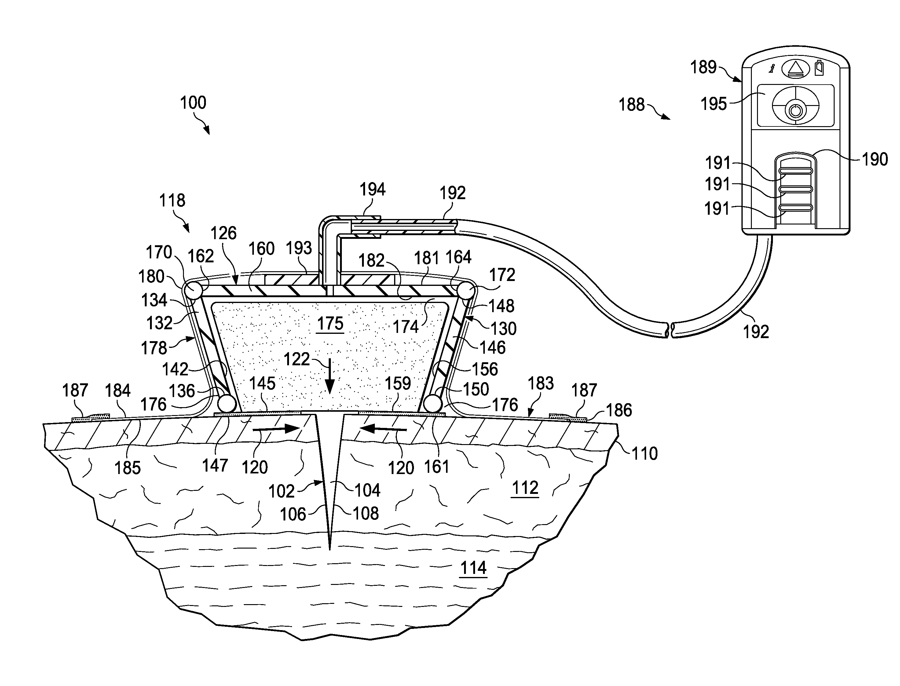
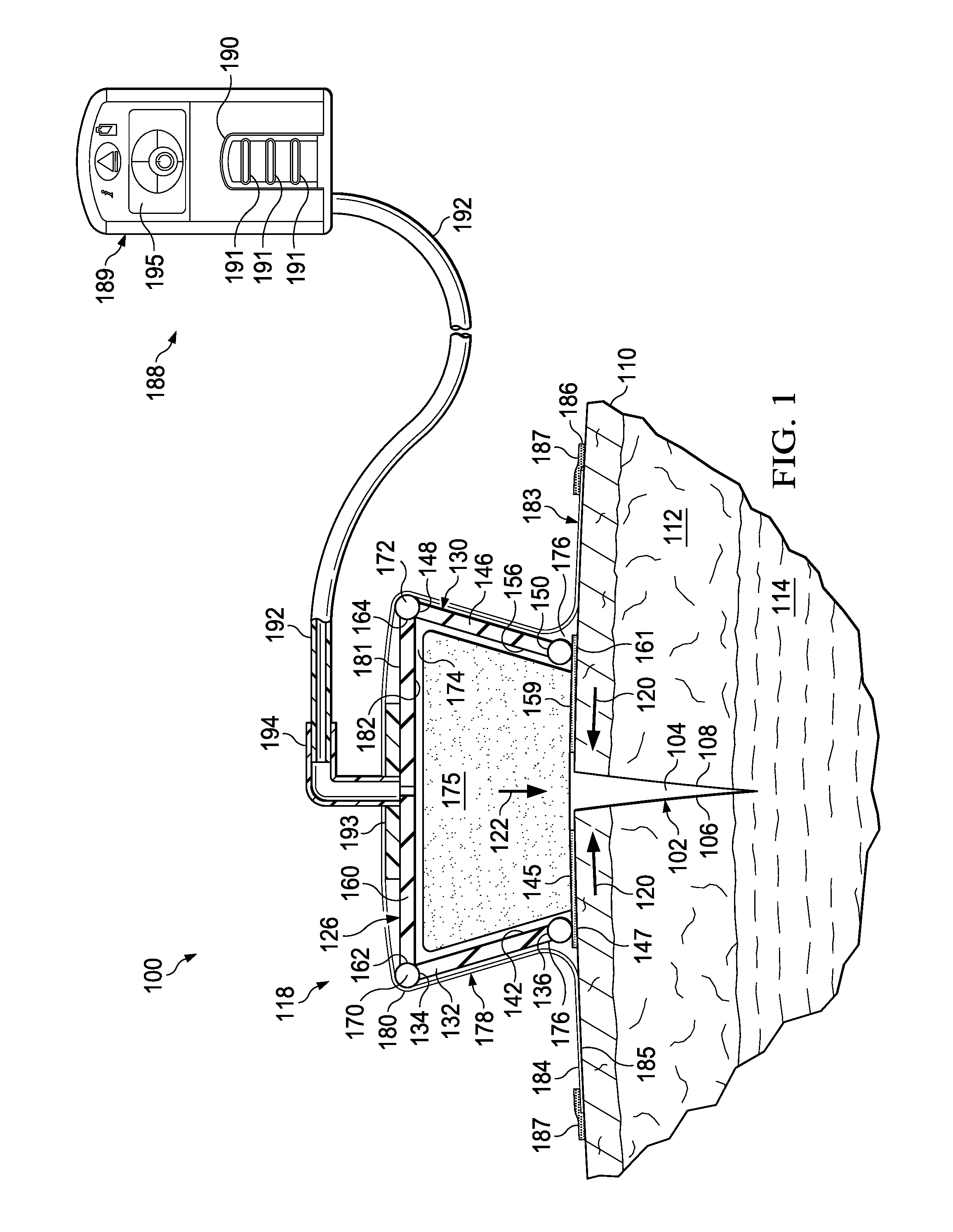
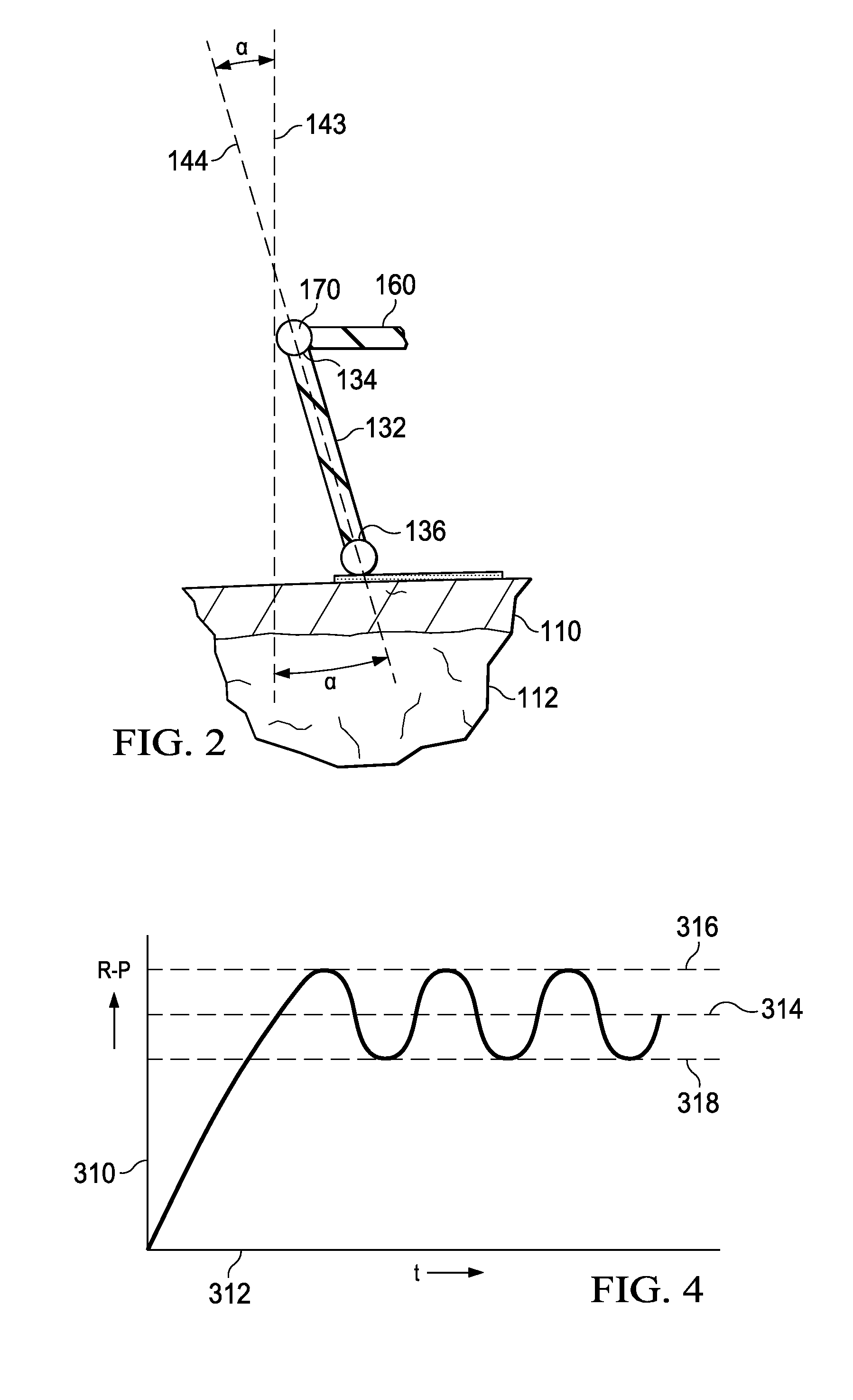
[0024]Referring to FIGS. 1 and 2 an illustrative embodiment of a reduced...


PUM

PropertyMeasurementUnit
pore sizesaaaaaaaaaa
elongation ratesaaaaaaaaaa
pressureaaaaaaaaaa

Abstract

A reduced-pressure, linear-wound closing bolster has a pivotable frame that moves from an extended position to a compressed position under the influence of reduced pressure. The closing bolster may have a first closing member, a second closing member, and an interior space. A manifold member is disposed within the interior space and may be coupled to the pivotable frame. When a reduced pressure is applied, the pivotable frame is urged from the extended position to the compressed position. A first gripping member for transmitting a closing force from the first closing member to a first edge of a linear wound may be attached. Likewise, a second gripping member for transmitting a closing force from the second closing member to a second edge of the linear wound may be attached. Systems and methods are also presented.

Description

RELATED APPLICATIONS[0001]The present invention claims the benefit, under 35 USC §119(e), of the filing of U.S. Provisional Patent Application Ser. No. 61 / 057,803, entitled “Reduced-Pressure, Linear-Wound Treatment System,” filed May 30, 2008; and U.S. Provisional Patent Application Ser. No. 61 / 078,114, entitled “Reduced-Pressure, Linear Wound Closing Bolster and System,” filed Jul. 3, 2008. All of these provisional applications are incorporated herein by reference for all purposes.BACKGROUND[0002]The present invention relates generally to medical treatment systems, and more particularly, to reduced-pressure, linear wound closing bolsters and systems.[0003]Physicians perform millions of surgical procedures each year around the world. Many of the procedures are performed as open surgery and an increasing number are performed using minimally invasive surgery, such as arthroscopic, laparoscopic, and endoscopic procedures. However performed, surgical procedures involve acute wounds, e.g...

Claims


Application Information

Patent Timeline
Patent Type & Authority Patents(United States)
IPC IPC(8): A61M1/00
CPCA61F13/0216A61F13/00068A61M1/0088A61B2017/00561A61B2017/081A61M1/0037Y10T29/49826A61M1/75A61M1/915A61B17/08A61F13/00017A61F13/00021A61M27/00
Inventor SEEGERT, CHARLES ALAN
Owner 3M INNOVATIVE PROPERTIES CO
Learn More