
Skid for a snow blower and a snow blower incorporating the same

a technology of snow blower and skid, which is applied in the direction of multi-purpose tools, vehicle components, construction, etc., can solve the problems of causing the damage of grinding and scraping caused by prior art skids

Inactive Publication Date: 2012-06-05
RAFTERY DESIGN
View PDF23 Cites 24 Cited by
  • Summary
  • Abstract
  • Description
  • Claims
  • Application Information

AI Technical Summary

Benefits of technology

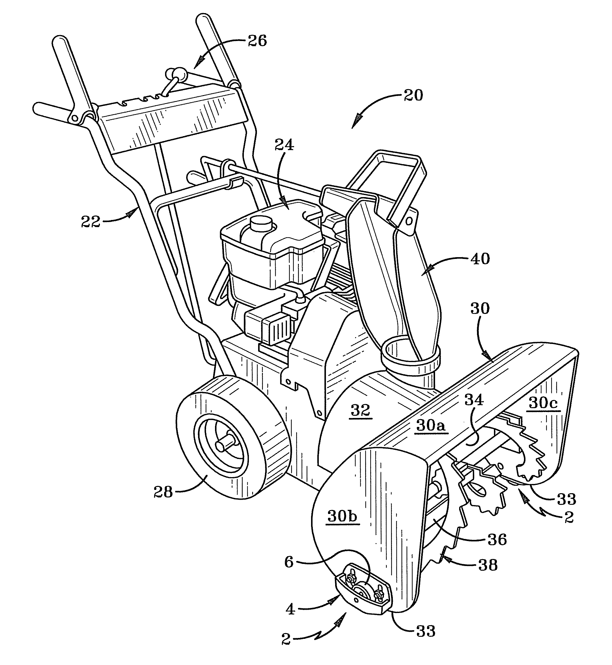
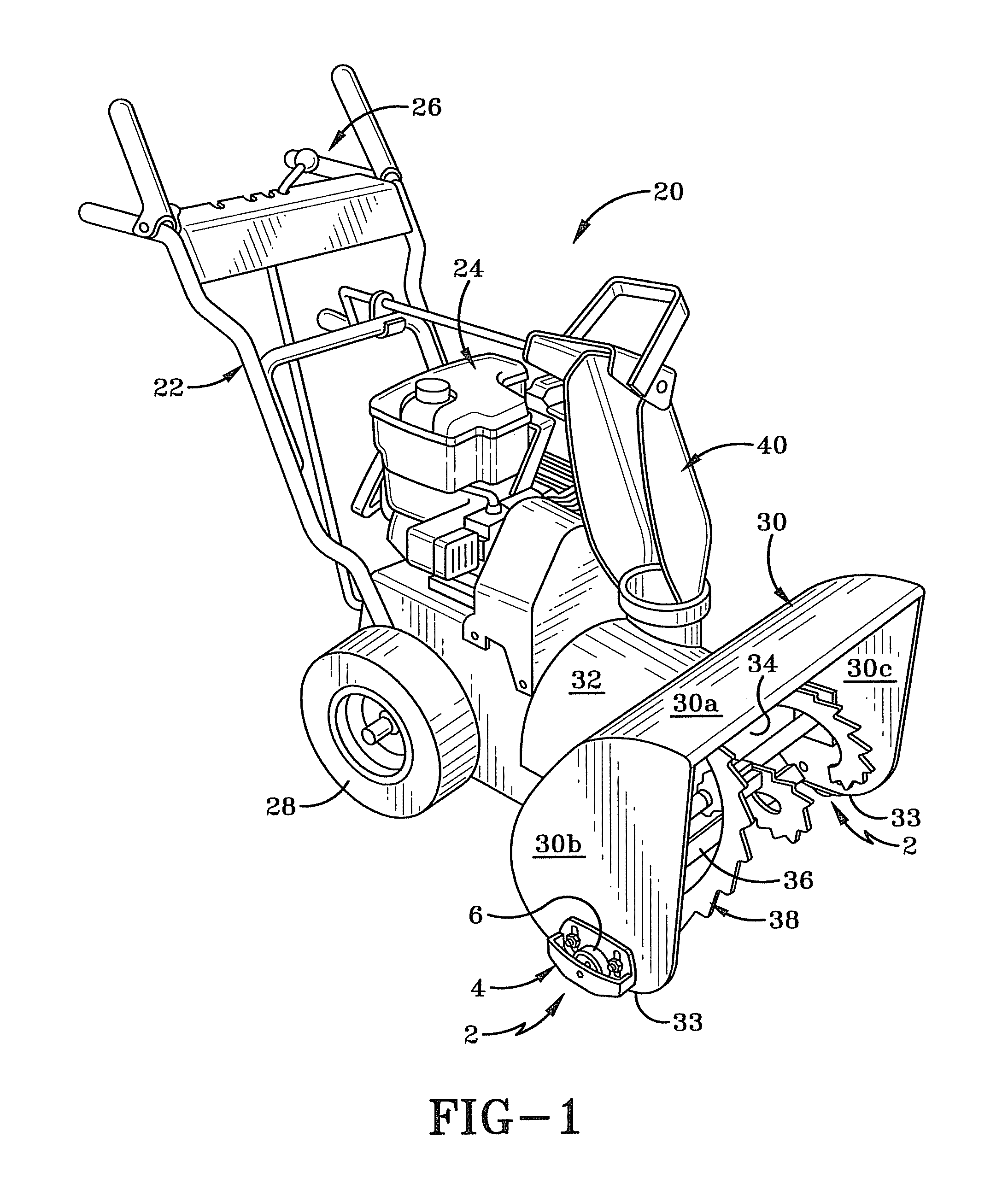
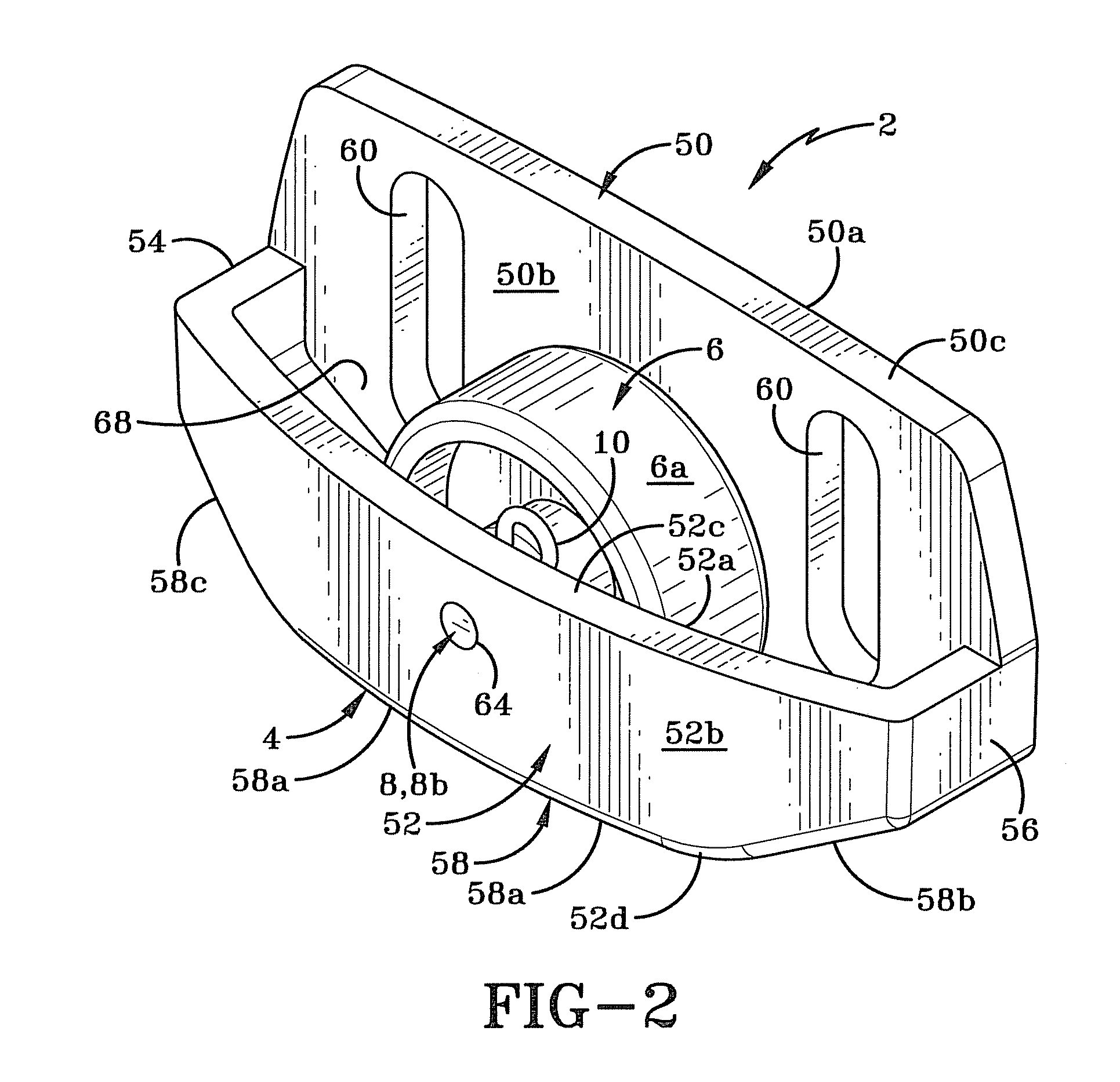
[0010]The device of the present invention comprises a skid for use on a snow blower, where the snow blower includes an auger housing through which snow removed from an area is channeled. The skid includes a body that is secured to a vertical side wall of the auger housing. The body includes a sliding surface which assists the auger housing in sliding over snow-covered regions of the area being cleared; and a rolling surface which assists the auger housing to travel over snow-free regions of the area being cleared. A slot is provided in the sliding surface of the skid and a portion of the rolling surface projects for a distance below the sliding surface. An adapter plate may be positioned between the body and the side wall of the auger housing. The adapter plate enables the body to be secured to different makes of auger housing.
[0011]The skid in accordance with the present invention improves mobility and handling of the snow blower on exposed surfaces, works in both forward and reverse directions and reduces wear and tear on the skid surface while preventing scuffing and marking to the surfaces being cleared. The grinding and scraping cause by prior art skids is particularly damaging when these types of devices are used on decorative, stamped concrete surfaces that are becoming ever more popular in the construction of driveways, walkways and patios.
[0012]The objective of the present invention is to provide a skid device for a snow blower that includes a wheel feature located on at least one, and preferably both, side walls at the front of the snow blower machine. The wheel feature allows the snow blower to roll over surfaces with greater mobility. It reduces wear to the skid surface and prevents scuffing of the surface to be cleared.

Problems solved by technology

The grinding and scraping cause by prior art skids is particularly damaging when these types of devices are used on decorative, stamped concrete surfaces that are becoming ever more popular in the construction of driveways, walkways and patios.

Method used


Image

  • Skid for a snow blower and a snow blower incorporating the same
  • Skid for a snow blower and a snow blower incorporating the same
  • Skid for a snow blower and a snow blower incorporating the same

Examples


first embodiment

[0059]Referring to FIGS. 14-17, there is shown an alternative method of securing skid 2 to a side wall 130b of auger housing 130 that includes utilizing adapter plate 80. Adapter plate 80 is utilized when the spacing between slots 60 does not correspond to the spacing between holes 135 on side wall 130b of auger housing 130. Adapter plate 80 makes it possible to mount skid 2 on a wide variety of different types of snow blowers that are made by different manufacturers.

[0060]In accordance with the present invention, adapter plate 80 is a substantially planar member having first and second side surfaces 80a, 80b. A first set of holes 84 is defined in adapter plate 80 and these holes extend between first side surface 80a and second side surface 80b. Holes 84 are oriented substantially at right angles to the longitudinal axis of the plate 80. (The longitudinal axis of the plate 80 is oriented substantially parallel to the longitudinal axis “Y” of skid 2.) Holes 80 preferably are generall...

second embodiment

[0064]FIG. 19 shows an adapter plate in accordance with the present invention, generally indicated at 200. Adapter plate 200 is manufactured from metal and is substantially thinner than adapter plate 80. Additionally, adapter plate 200 includes a planar first region 202 and a planar second region 204 that are each vertically oriented and are horizontally offset relative to each other. First and second regions 202, 204 are joined together by a third region 203 that is disposed horizontally between them. Third region 203 is of a depth that is sufficient to ensure that the head of bolt 174 will not project passed the surface 204a of second region 204, and so that the head of bolt 90 will not project passed surface 202b of first region 202. First region 202 defines a pair of generally circular holes 206 therein. Holes 206 are spaced a first distance longitudinally from each other and extend between first surface 202a and second surface 202b of first region 202. Second region 204 defines...

third embodiment

[0066]FIG. 20 shows an adapter plate in accordance with the present invention and is generally indicated at 300. Adapter plate 300 comprises a planar member that has a first surface 300a and a second surface 300b. A first threaded rod 302 extends outwardly from second surface 300b in a first direction and a second threaded rod 304 extends outwardly from first surface 300a in a second direction. First and second rods are vertically and horizontally offset relative to each other. This makes it possible for adapter plate 300 to be rotated to match the spacing between holes 135 and slots 60 on different snow blowers and skids 2. First rods 302 are received through the slots 60 and second rods 304 are received through holes 135. Adapter plates 300 are secured to first side wall 50 of skid by inserting first rod 302 through one of the slots 60 and then a washer 78 and nut 79 are engaged therewith so that adapter plate 300 is loosely engaged with skid. When both adapter plate 300 have been...


PUM


Abstract

A skid for use on a snow blower, where the snow blower includes an auger housing through which snow removed from an area is channeled. The skid includes a body that is secured to a vertical side wall of the auger housing. The body includes a sliding surface which assists the auger housing in sliding over snow-covered regions of the area being cleared; and a rolling surface which assists the auger housing to travel over snow-free regions of the area. A slot is provided in the sliding surface of the skid and a portion of the rolling surface projects for a distance below the sliding surface. An adapter plate may be positioned between the body and the side wall of the auger housing. The adapter plate enables the body to be secured to different makes of auger housing.

Description

CROSS-REFERENCE TO RELATED APPLICATION[0001]This invention claims the benefit of U.S. Provisional Patent Application No. 61 / 359,066, filed Jun. 28, 2010, the entire specification of which is incorporated herein by reference.BACKGROUND OF THE INVENTION[0002]1. Technical Field[0003]This application relates generally to snow removal devices. More particularly, the invention relates to snow blowers. Specifically, the invention relates to a skid that is attached to the auger housing on the snow blower; where the skid includes sliding surface and a rolling surface that assist the auger housing to travel more easily over both snow covered regions and snow-free regions of the area being cleared, thereby making the blower easier to operate and less prone to damage during operation.[0004]2. Background Information[0005]A snow blower is a machine that is designed to lift snow and ice off a surface and to blow or throw the same some distance from the area that is being cleared. There are essenti...

Claims


Application Information

Patent Timeline
Patent Type & Authority Patents(United States)
IPC IPC(8): E01H5/06
CPCE01H5/045E01H5/066E01H5/098E01H5/12Y10T16/218Y10T16/19Y10T16/216
Inventor RAFTERY, WILLIAM BARRET
Owner RAFTERY DESIGN
Learn More