Method and apparatus for monitoring respiration

a technology of respiration monitoring and apparatus, applied in the field of physiological monitors, can solve the problems of poor adherence to guidelines for cardiopulmonary resuscitation, inability to detect the presence of oxygen in the air,

Active Publication Date: 2012-06-05
LAERDAL MEDICAL AS
View PDF11 Cites 16 Cited by
  • Summary
  • Abstract
  • Description
  • Claims
  • Application Information

AI Technical Summary

Problems solved by technology

In some cases, patients with respiratory problems may be unstable and risk losing their respiratory function.
However, such systems—commonly using a differential pressure flow sensor, or end tidal CO2 sensor—are often too expensive or not readily available in simple mask-and-oxygen scenarios commonly used out-of-hospital.
A common problem in situations where a rescuer will provide ventilations to a patient, e.g. during cardiac arrest, is poor adherence to guidelines for cardiopulmonary resuscitation (CPR).
Often, the patient is hyperventilated which is deleterious to the patient.
However, impedance signals are often highly susceptible to noise (e.g. compression artifacts) and baseline drift problems requiring advanced and often expensive solutions.
Also, the ventilation volume can not be measured using an impedance signal due to the variations of human physiology.
However, in order to achieve a high level of accuracy, this method requires a restriction with a very sophisticated geometry.
This may often be forbiddingly expensive for a single-use unit.
The Venturi principle also has the disadvantage that two pressure outlets are needed from the restriction, which may complicate the geometry and increase cost.
In addition, two pressure sensors are needed to measure the pressure drop in the restriction, which may increase cost.
If a differential pressure sensor is used, the output from the sensor can, however, only be used to assess flow, and not to monitor the absolute airway pressure, which may be important for detecting mask leakage, airway occlusion etc.
Additionally, Venturi measurements are also known to be unstable in conditions of turbulent flow.

Method used


Image

  • Method and apparatus for monitoring respiration
  • Method and apparatus for monitoring respiration
  • Method and apparatus for monitoring respiration

Examples


Embodiment Construction

[0016]Certain details are set forth below to provide a sufficient understanding of embodiments of the invention. However, it will be clear to one skilled in the art that embodiments of the invention may be practiced without these particular details. Moreover, the particular embodiments of the present invention described herein are provided by way of example and should not be used to limit the scope of the invention to these particular embodiments.

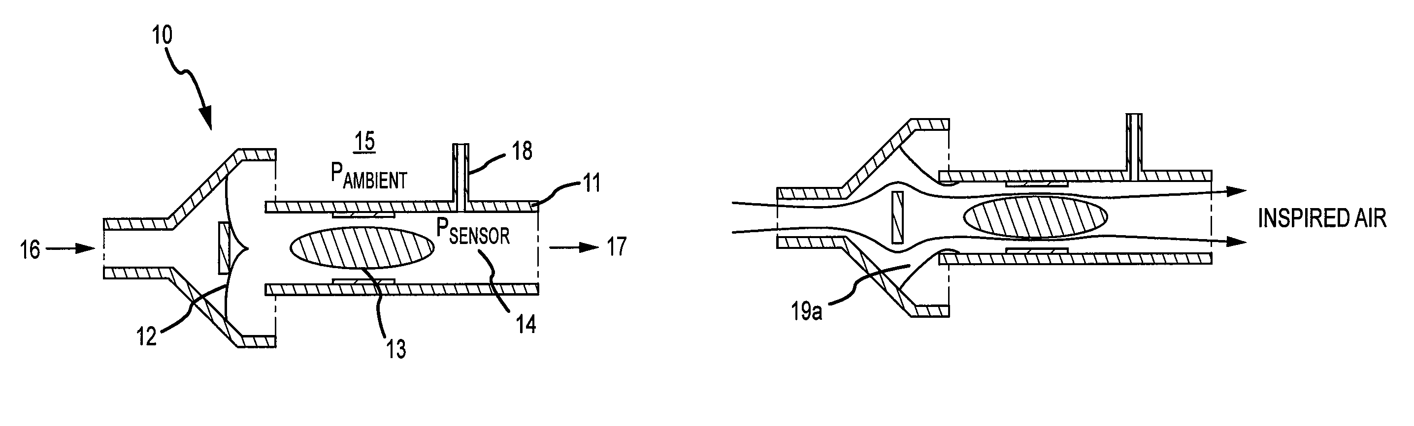
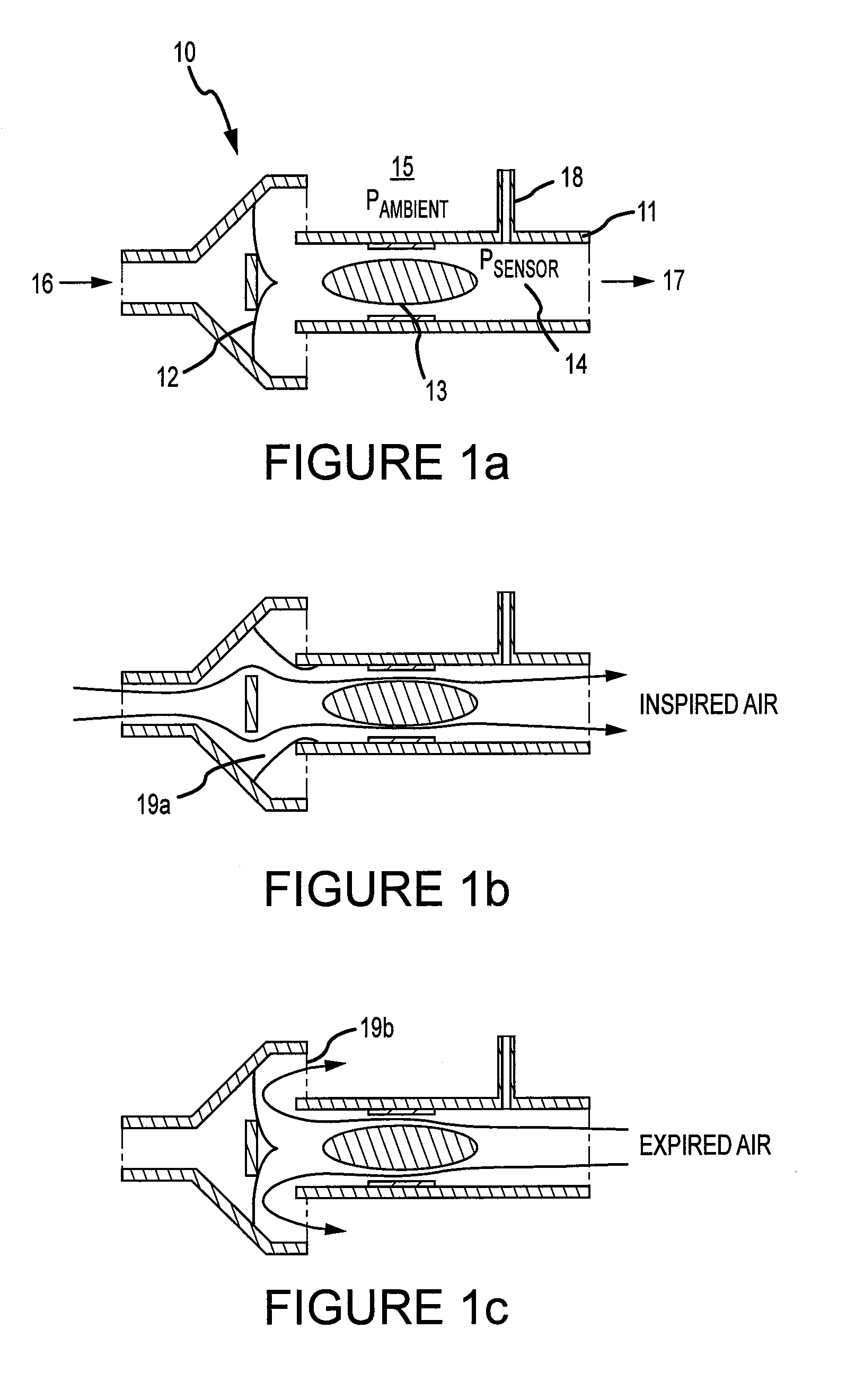
[0017]FIG. 1a illustrates a monitoring device 10 in accordance with an embodiment of the invention. The monitoring device 10 may include a duct 11 and a restriction 13 arranged inside the duct 11, restricting the fluid (e.g., gas, air, or other fluidal substance) flow in the duct. A resuscitator bag / bellow 16 and a patient interface 17, such as a face / respiratory mask, are connected to the monitoring device 10 on opposite ends of the duct 11. The monitoring device 10 may further include a pressure sensor 14 arranged in the duct at the patie...


PUM


Abstract

A device for monitoring respiration comprises a duct, a flow restricting element in the duct, and a pressure sensor arranged in the duct. The pressure sensor measures a pressure drop across the flow restricting element as a pressure difference between a pressure at a location in the duct on a first side of the flow restricting element and a substantially constant pressure on a second side of the flow restricting element opposite the first side.

Description

CROSS-REFERENCE TO RELATED APPLICATIONS[0001]This application claims the benefit of U.S. Provisional Application No. 60 / 887,819, filed Feb. 2, 2007, and GB Application No. 0702078.7, filed Feb. 2, 2007. The entire disclosure of the prior applications are considered to be part of the disclosure of the instant application and are hereby incorporated by reference therein.TECHNICAL FIELD[0002]Embodiments of the invention relate to physiological monitors, and, more particularly, to respiration monitoring apparatus and methods thereof.BACKGROUND OF THE INVENTION[0003]In many situations there is a need for monitoring a patient's respiration or to provide ventilations to a patient that is not breathing. Such situations might include cardiac arrest, respiratory obstruction, asthma, chronic obstructive pulmonary disease (COPD), heart failure, major trauma, overdose, seizure, sepsis and during anesthesia. In the following description the term “respiration” includes both spontaneous and assiste...

Claims


Application Information

Patent Timeline
Patent Type & Authority Patents(United States)
IPC IPC(8): A61B5/08
CPCA61B5/087A61B5/093A61B5/412A61M16/0051A61M16/0084A61M16/0858A61M2230/04A61M2230/205A61M2230/432A61M2230/46A61M2230/65A61M16/0078A61M16/06A61M16/0816A61M16/208A61M2016/0027A61M2016/0042A61M16/0866A61M16/024A61M16/00
Inventor MYKLEBUST, HELGEEILEVSTJONN, JOARNYSAETHER, JON
Owner LAERDAL MEDICAL AS
Why Eureka
Try Eureka