Tamper resistant power receptacle having a safety shutter

a technology of safety shutter and power receptacle, which is applied in the direction of gaseous cathode, electrical apparatus casing/cabinet/drawer, coupling device connection, etc., can solve the problems of electrical shock, electrical conductor corrosion in open holes, electrical shock, etc., and achieve wide applicability and reliability. compact

Inactive Publication Date: 2012-06-05
BINGHAM MCCUTCHEN +1
View PDF24 Cites 33 Cited by
  • Summary
  • Abstract
  • Description
  • Claims
  • Application Information

AI Technical Summary

Benefits of technology

[0011]An object of the present invention is to provide a tamper resistant power receptacle that is reliable and compact and has wide applicability.

Problems solved by technology

The electrical conductors in open holes may corrode due to the moisture in the air, or their electrical conductivity may be affected by dust accumulation.
Moreover, if used improperly, or if children play with the receptacle, conductive foreign objects may be inserted into the hole.
This can cause electrical shock and is of great safety concern.
Such plastic biasing members tend to be unreliable as the material may become fatigued due to repeated use and various environmental factors.
Thus, the elasticity of the plastic material may be lost and the shutters may fail to close.
Further, the plastic biasing members are bulky and increase the overall size of the receptacle.
Such springs also tend to be bulky.
As another example, in the tamper resistant receptacle described in Chinese patent CN 99254384.3, the biasing member used in the safety mechanism is an F-shaped metal plate, which tends to become fatigued or broken due to repeated use.
Further, the biasing member and the safety mechanism are installed separately, making it inconvenient to install and replace and limiting its applicability.
Some other tamper resistant receptacles have complicate structures and are costly to manufacture.

Method used


Image

  • Tamper resistant power receptacle having a safety shutter
  • Tamper resistant power receptacle having a safety shutter
  • Tamper resistant power receptacle having a safety shutter

Examples


Embodiment Construction

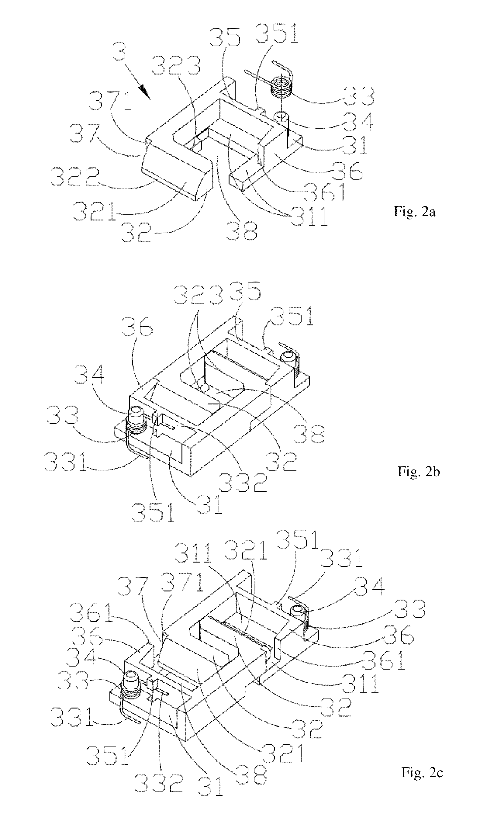
[0025]In the drawings and the descriptions below, similar components of the embodiments are labeled with similar or the same reference symbols. In addition, the sliding mechanism is formed by two identically shaped sliding blocks cooperating with each other, and in some figures reference symbols are provided for one of the sliding blocks.

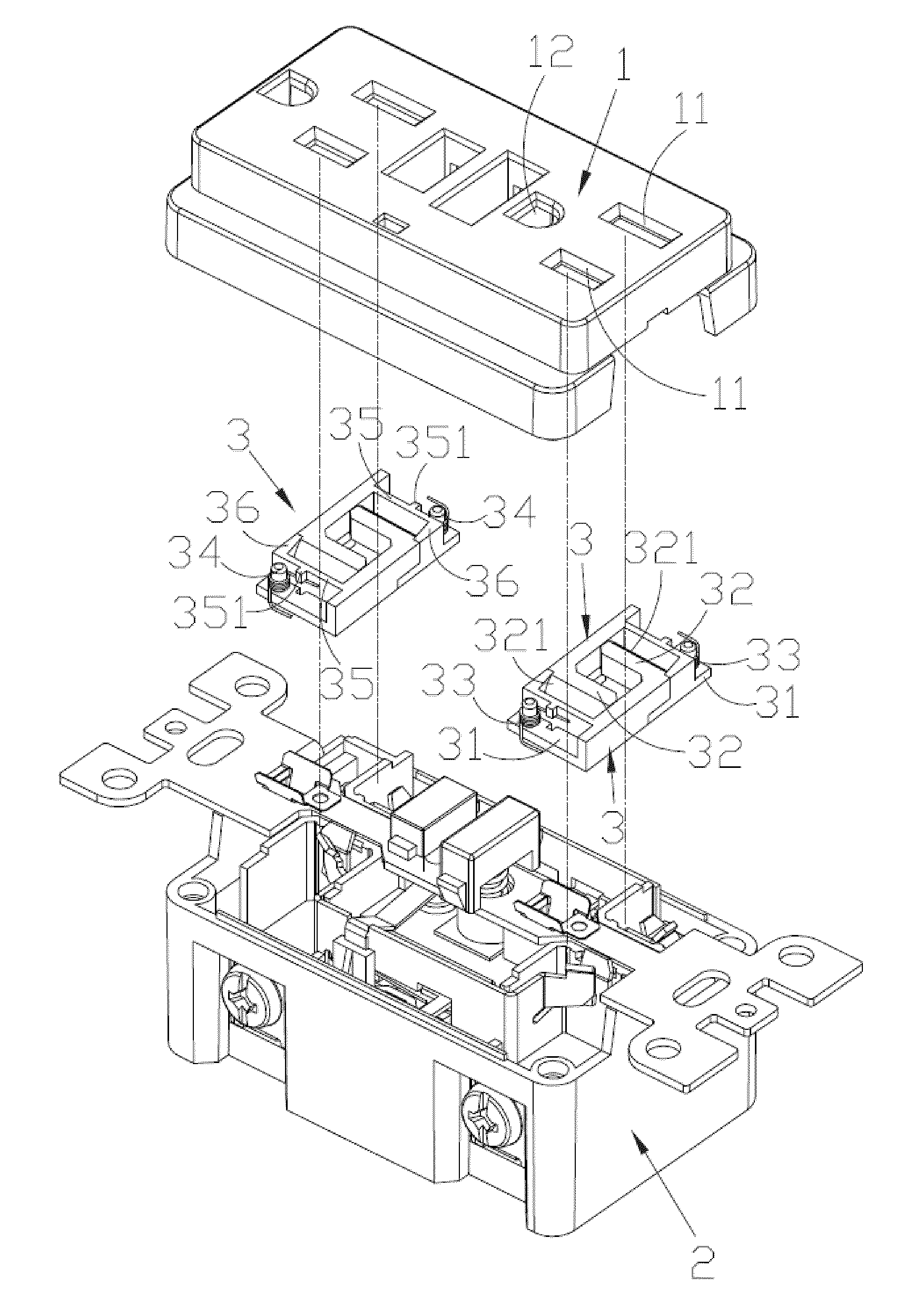
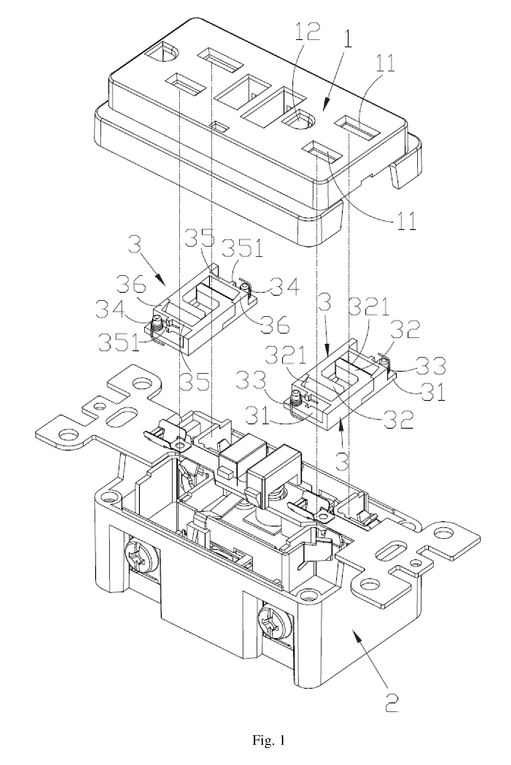
[0026]Referring to FIG. 1, a tamper resistant receptacle incorporating a safety shutter according to embodiments of the present invention includes a cover 1 and a base 2 removably coupled to the cover. The cover 1 has hot and neutral holes 11 and a ground hole 12. The base 2 includes hot and neutral conductors 21 and ground conductors 22 corresponding to the hot and neutral holes 11 and the ground hole 12. The safety shutter is disposed between the cover 1 and the base 2, preferably aligned with the hot and neutral holes 11. The safety shutter includes two identically shaped sliding blocks 3 and corresponding biasing member.

[0027]FIGS. 2a-2c show th...


PUM


Abstract

A safety shutter for a power receptacle includes two identical sliding blocks engaged with each other and two biasing members. Each sliding block has a base and a platform extending from the base with a slanted surface. The slanted surfaces are disposed below the holes of the receptacle. The biasing members are helical torsion springs disposed at the end of the sliding blocks. The platform of each sliding block is disposed above the base of the other sliding block so the shutter normally blocks access to the conductors inside the receptacle. When two prongs of a plug are inserted into both holes, the prongs push on both slanted surfaces, causing the shutter to open. When a foreign object is inserted into only one hole, only one sliding block is moved by the foreign object and the base of the other sliding block still blocks access to the conductors.

Description

BACKGROUND OF THE INVENTION[0001]1. Field of the Invention[0002]This invention relates to a power receptacle, and in particular, it relates to a receptacle with a safety shutter providing tamper resistance.[0003]2. Description of the Related Art[0004]Conventional power receptacle such as wall receptacles or extension cord receptacles have one or more holes to receive plugs. The electrical conductors in open holes may corrode due to the moisture in the air, or their electrical conductivity may be affected by dust accumulation. Moreover, if used improperly, or if children play with the receptacle, conductive foreign objects may be inserted into the hole. This can cause electrical shock and is of great safety concern.[0005]To solve the above problem, tamper resistant receptacles have been developed. However, these tamper resistant receptacles have various shortcomings.[0006]For example, in the tamper resistant receptacle described in U.S. Pat. No. 4,379,607, a plastic biasing member is...

Claims


Application Information

Patent Timeline
Patent Type & Authority Patents(United States)
IPC IPC(8): H01R13/46
CPCH01R13/4534H01R13/5213H01R13/652H01R24/78H01R25/003H01R25/006H01R2103/00
Inventor LI, CHENG-LI
Owner BINGHAM MCCUTCHEN
Why Eureka
Try Eureka