

Volumetric metering system with clutch based sectional shut-off
a technology of sectional shut-off and metering system, which is applied in the direction of furrow making/covering, centrifugal wheel fertilisers, potato planters, etc., can solve the problem that the arrangement does nothing to address
- Summary
- Abstract
- Description
- Claims
- Application Information
AI Technical Summary
Benefits of technology
Problems solved by technology
Method used
Image

Examples
Embodiment Construction
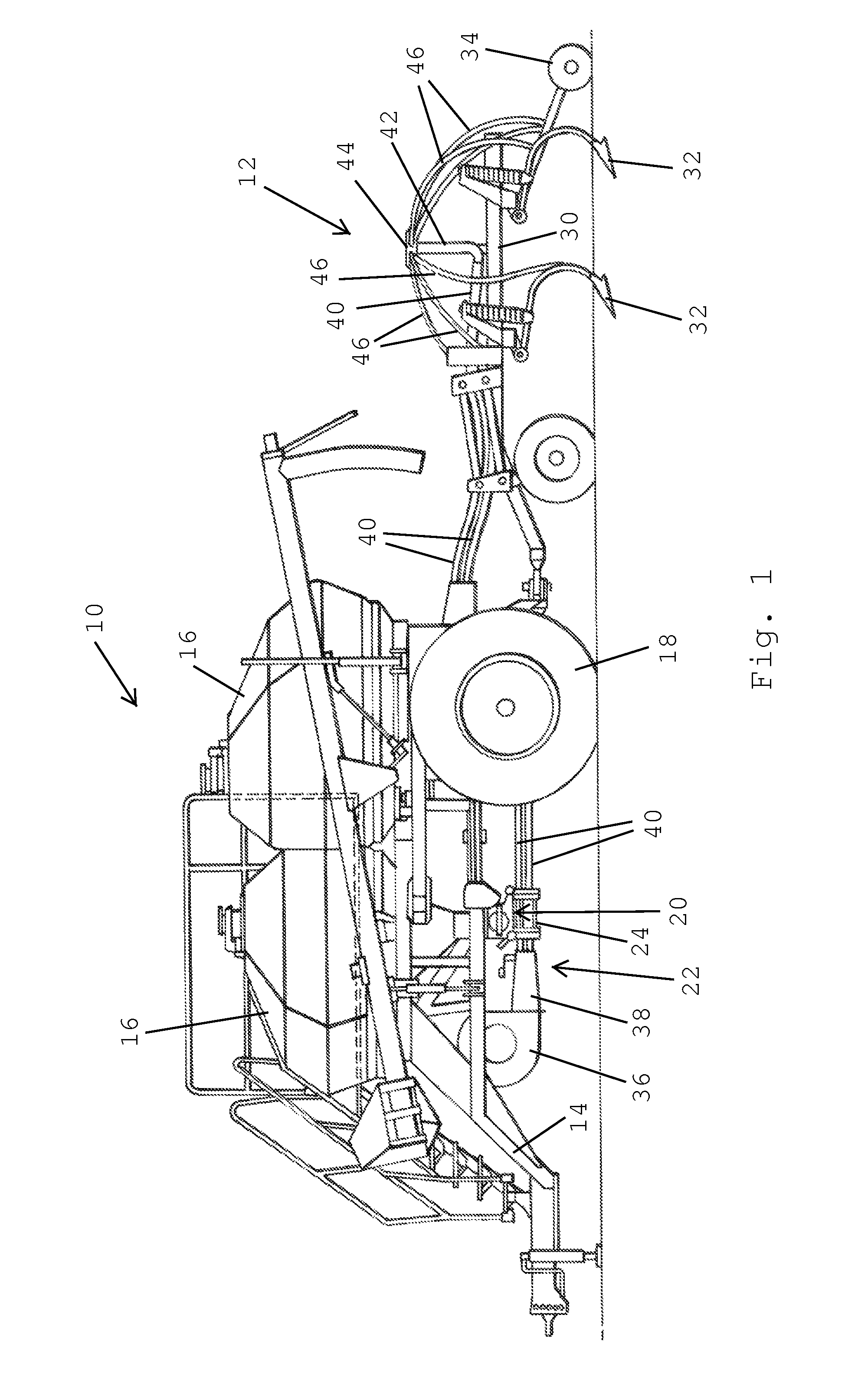
[0015]An air seeder constructed according to a preferred embodiment of the present invention is shown in the figures. With reference to FIG. 1, an air seeder is shown comprising of a seed cart 10 towed between a tractor (not shown) and a tilling implement 12. The seed cart 10 has a frame 14 to which product tanks 16 and wheels 18 are mounted. Each product tank 16 has an associated metering system 20 at its lower end for controlled feeding of product into a pneumatic distribution system 22 at a primary distribution manifold 24. The tilling implement 12, towed behind the seed cart 10, consists generally of a frame 30 to which ground openers 32 are mounted. Incorporation of seed row finishing equipment such as closing wheels 34 is also desirable in many applications.
[0016]The pneumatic distribution system 22 includes a centrifugal fan 36 connected to a plenum 38, which is in turn connected to one or more primary distribution manifolds 24, each associated with a product tank 16. The ind...
PUM
 Abstract
Description
Claims
Application Information