Process of manufacturing composite structures with embedded precured tools

a composite structure and precured technology, applied in the field of composite structure manufacturing, can solve the problems of variable complexity level, increased final product weight, complex and therefore expensive and difficult to use tool system, etc., and achieve the effect of high integration level

Inactive Publication Date: 2012-06-12
AIRBUS OPERATIONS SL
View PDF10 Cites 1 Cited by
  • Summary
  • Abstract
  • Description
  • Claims
  • Application Information

AI Technical Summary

Benefits of technology

[0016]The process of manufacturing organic matrix composite structures according to the present invention can be understood as a subcomponent co-curing or co-bonding process that reduces or eliminates the use of complex tools both inside and outside the vacuum bag.
[0018]One advantage of the process of the invention is that it opens up the possibility of manufacturing structures with a high integration level by using tools that become built into the structure itself and simple tools on the outside, which can even be eliminated in certain structural configurations. The built-in tool may further be designed so as to allow a double function as a tool and as a supporting structure of the load for which the piece was designed.

Problems solved by technology

This has forced and continues to force the development of manufacturing processes capable of producing components with the required quality in a repetitive manner and with a manufacturing cost that is appropriate for the component to be manufactured.
It can generally be considered that a large integration of components in a single manufacturing cycle implies a very complex and therefore expensive and difficult to use tool system.
However, this last system has obvious disadvantages from the point of view of the complexity of the production system as a large number of components must be worked with, and from the point of view of the structure itself as it implies complex surface preparation systems prior to bonding and, of course, a final product weight increase.
The known processes of manufacturing organic matrix and continuous fiber composite structures, using both co-cured, co-bonding or secondary bonding systems, are always based on oven, vacuum bag and / or autoclave curing systems with a tool that is external to the component to be manufactured, which has a variable complexity level according to the complexity and level of responsibility of the final piece to be manufactured.

Method used


Image

  • Process of manufacturing composite structures with embedded precured tools
  • Process of manufacturing composite structures with embedded precured tools

Examples


Embodiment Construction

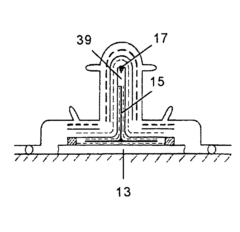
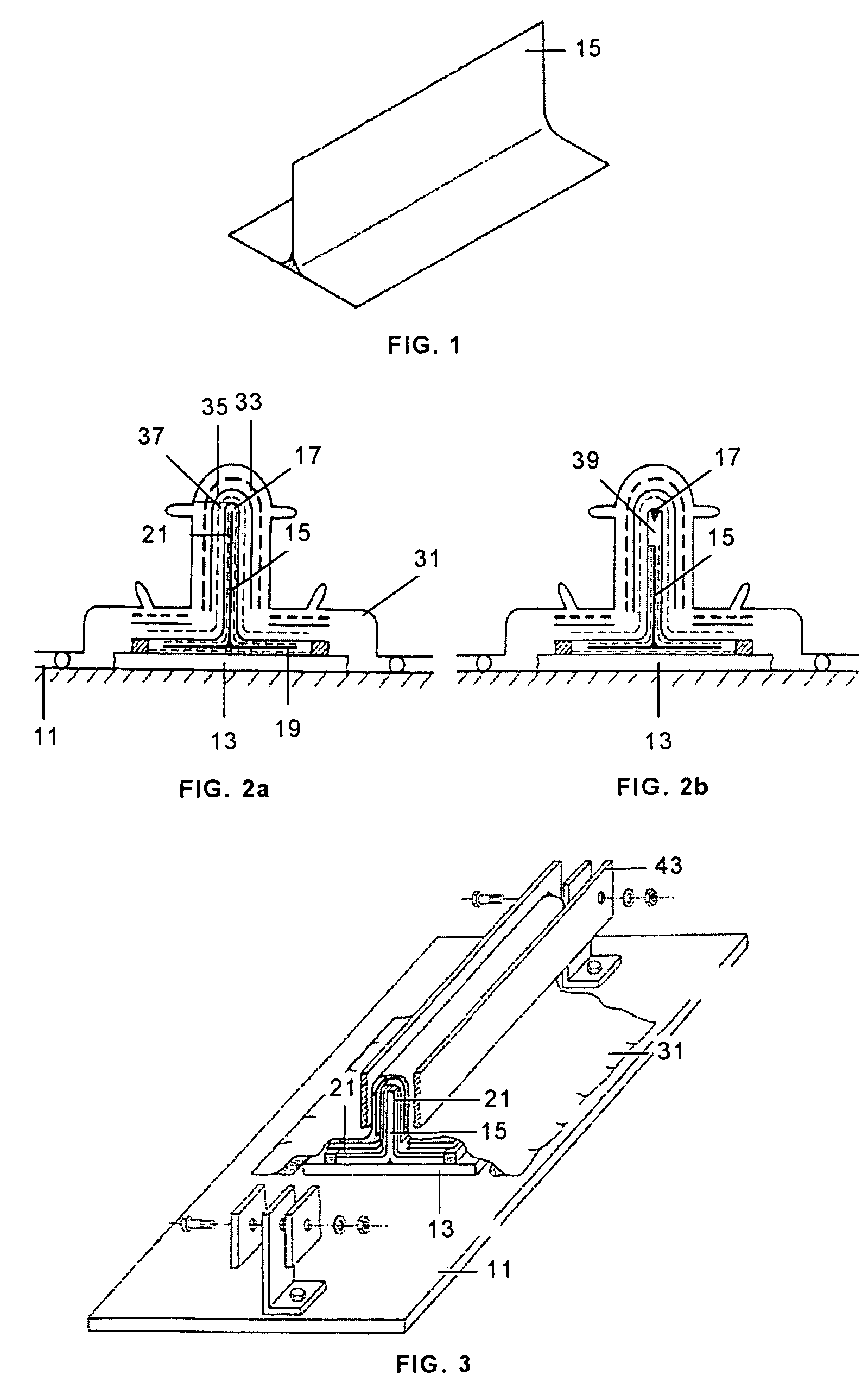
[0023]The process of manufacturing composite structures according to the present invention is particularly applicable to the manufacture of planar or curved structures with T-, Ω- or H-shaped stiffeners, and described below is the case of a planar structure stiffened with T-shaped stringers.

[0024]A precured T-shaped component 15 (see FIG. 1) made of planar carbon fiber fabric preimpregnated with epoxy resin, with a thickness exceeding 0.4 mm is used as the tool that will remain built into the structure. The tool 15 can be continuous or discontinuous, depending on the shape of the final structure to be manufactured.

[0025]The process is carried out on a table 11 on which the planar structure 13, the first subcomponent of the structure, is arranged.

[0026]The tool 15 is positioned on the planar structure 13, being able to use an auxiliary means 19 between them, such as an adhesive film or layer of preimpregnated material. The tool 15 may require treatment prior to the bonding process pr...


PUM

PropertyMeasurementUnit
thicknessaaaaaaaaaa
shapeaaaaaaaaaa
pressureaaaaaaaaaa

Abstract

The present invention relates to a process for manufacturing composite structures formed by two subcomponents of the same material, characterized in that it comprises the following steps: providing a first subcomponent (13), particularly a skin; providing a tool (15) made of a composite and precured for the manufacture of the second subcomponent (17), particularly a stiffener; positioning said tool (15) on said first subcomponent (13); applying preimpregnated composite (21) on said tool (15) so as to form the second subcomponent (17); consolidating the composite structure by means of a process of curing the assembly resulting from the previous steps under suitable pressure and / or temperature conditions.

Description

FIELD OF THE INVENTION[0001]The present invention relates to a process of manufacturing composite structures, and more particularly to a process in which at least one tool used for shaping one of its subcomponents remains embedded in the structure.BACKGROUND OF THE INVENTION[0002]In the aerospace industry today, mainly organic matrix, and continuous fibers composites based on epoxy resins and carbon fibers are widely used.[0003]The level of use of this type of structures has been gradually increasing, particularly in the aeronautics industry, to a point where epoxy matrix and carbon fiber composites can be considered the option used most in a wide variety of structural components. This has forced and continues to force the development of manufacturing processes capable of producing components with the required quality in a repetitive manner and with a manufacturing cost that is appropriate for the component to be manufactured. The tool plays a fundamental role in this aspect, so the...

Claims


Application Information

Patent Timeline
Patent Type & Authority Patents(United States)
IPC IPC(8): B29C43/28B29D99/00
CPCB29C66/43441B29C66/721B29C70/342B29C66/81455Y10T156/103Y10T156/1028Y10T156/1051B29K2105/246B29C66/7212B29C66/71B29C66/72141B29C66/73752B29C66/73941B29C65/02B29D99/0003B29C66/1122B29K2307/04B29K2309/08B29K2277/10B29K2063/00B29K2031/00B29K2061/04B29K2079/08
Inventor GARATE FEL, ENRIQUEREDONDO VARA, ENRIQUESANCHEZ GOMEZ, JOSERUISECO SALGADO, RAFAELSERRANO VELAZ, CESAR
Owner AIRBUS OPERATIONS SL
Why Eureka
Try Eureka