
Receiver structure and method for the demodulation of a quadrature-modulated signal

a quadrature-modulated signal and receiver technology, applied in the direction of amplitude demodulation, pulse manipulation, pulse technique, etc., can solve the problems of high data rate and inability to achieve optimal equalization in the electrical domain, and achieve the effect of accurate determination of the transmitted signal sequen

Active Publication Date: 2012-06-12
XIEON NETWORKS SARL
View PDF10 Cites 80 Cited by
  • Summary
  • Abstract
  • Description
  • Claims
  • Application Information

AI Technical Summary

Benefits of technology

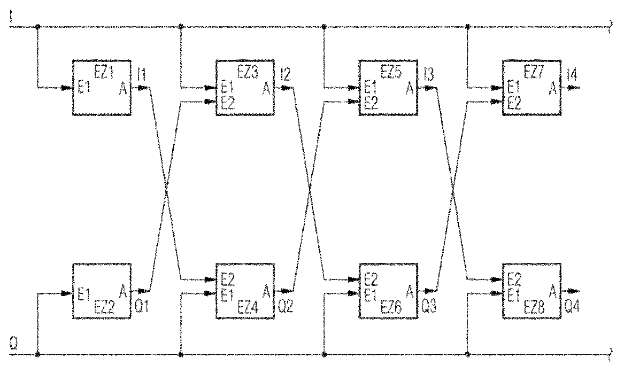
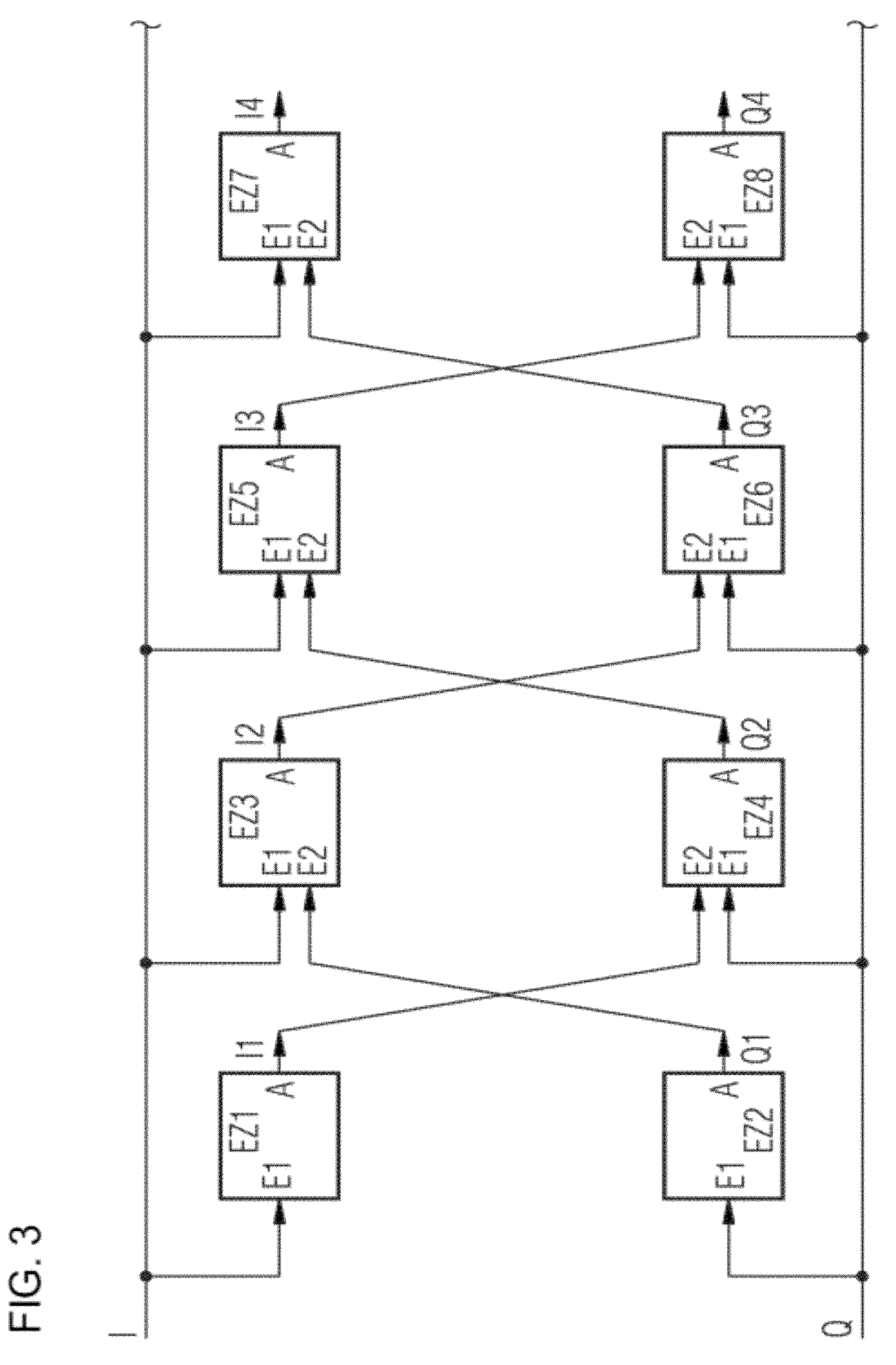
[0017]In one embodiment of the invention, the in-phase signal is determined by a cross-connected arrangement of several equalizers, taking into consideration the quadrature signal determined, and vice versa, as a result of which a more accurate determination of the transmitted signal sequence is possible. Furthermore, this determination can be implemented in a simple and economic manner particularly in the case of optical transmission, even at high data rates.

Problems solved by technology

An optimum equalization which may be achievable in the electrical domain is not possible, in particular, in the optical transmission with correspondingly high data rates.

Method used


Image

  • Receiver structure and method for the demodulation of a quadrature-modulated signal
  • Receiver structure and method for the demodulation of a quadrature-modulated signal
  • Receiver structure and method for the demodulation of a quadrature-modulated signal

Examples


Embodiment Construction

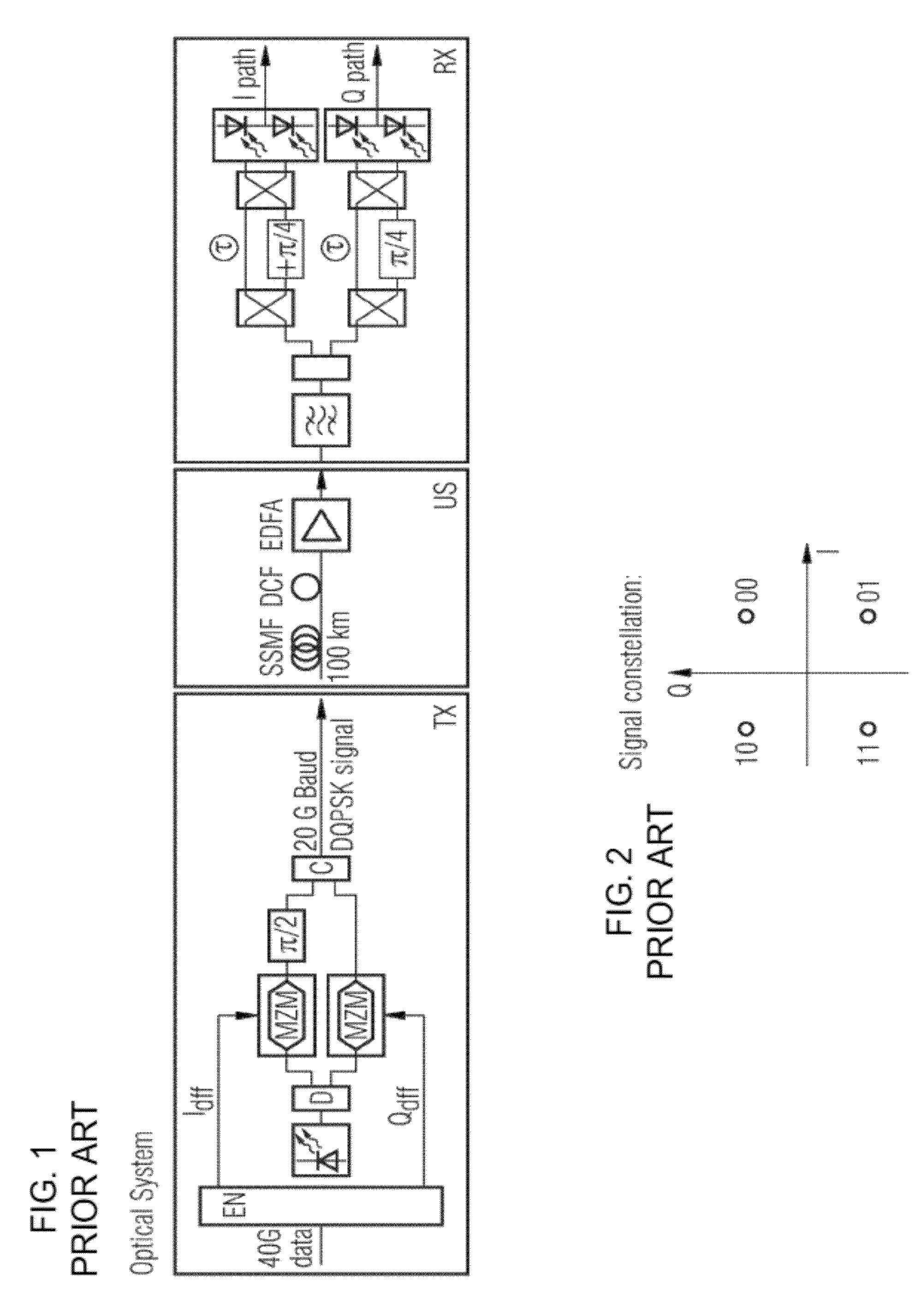
[0025]FIG. 1 shows an optical transmission system according to the prior art, already described in the introduction. FIG. 2 shows a signal constellation, already described, for a QPSK signal or quadrature phase shift keying signal, respectively.

[0026]FIG. 3 shows a block diagram of the arrangement according to the invention for evaluating the in-phase and quadrature signal. It has eight equalizers EZ1 to EZ8. The in-phase signal is in each case supplied to equalizers EZ1, EZ3, EZ5 and EZ7 at their first input E1. The quadrature signal Q is in each case supplied to equalizers EZ2, EZ4, EZ6, and EZ8 at their first inputs E1. The output signal I1 of the first equalizer EZ1 is supplied to a second input of the fourth equalizer EZ4. The output signal Q1 of the second equalizer EZ2 is supplied to a second input of the third equalizer EZ3. The output signal I2 of the third equalizer EZ3 is supplied to a second input of the sixth equalizer EZ6. The output signal Q2 of the fourth equalizer E...


PUM


Abstract

A receiver is provided for a quadrature-modulated signal, which can be divided into an inphase signal and a quadrature signal. The inphase signal is fed to first and third equalizers, and the quadrature signal is fed to second and fourth equalizers, wherein the first and second equalizers each perform a first equalization of the respective signal. An output of the first equalizer is connected to a second input of the fourth equalizer, which, by means of a second equalization of the quadrature signal, transmits an equalized quadrature signal as a function of the previously fed equalized inphase signal of the first equalizer. An output of the second equalizer is connected to the second input of the third equalizer, which, through a second equalization of the inphase signal, transmits an equalized inphase signal as a function of the previously fed equalized quadrature signal of the second equalizer.

Description

CLAIM FOR PRIORITY[0001]This application is a national stage application of PCT / EP2007 / 056810, filed Jul. 5, 2007, which claims the benefit of priority to German Application No. 10 2006 032 786.1, filed Jul. 14, 2006, the contents of which hereby incorporated by reference.TECHNICAL FIELD OF THE INVENTION[0002]The invention relates to a receiver and method for demodulating a quadrature-modulate signal.BACKGROUND OF THE INVENTION[0003]Digital information is transmitted by one or more signals using a multiplicity of methods. To generate a signal with digital information, so called digital modulation methods are used. In these methods the binary information is impressed or modulated onto a carrier. It is a characteristic of the digital modulation methods that only discrete amplitude, phase or frequency values are used for the impression, such a discrete value corresponding to a binary value or a binary sequence. In principle, these digital modulation methods are divided into amplitude s...

Claims


Application Information

Patent Timeline
Patent Type & Authority Patents(United States)
IPC IPC(8): H03H7/30
CPCH04L25/03012H04L27/223H04L2025/03439
Inventor HAUSKE, FABIANLANKL, BERTHOLDSCHMIDT, ERNST-DIETERXIE, CHANGSONG
Owner XIEON NETWORKS SARL
Learn More