Telescoping tube system for a vacuum cleaner

a technology of telescopic tubes and vacuum cleaners, which is applied in the direction of screw thread joints, cleaning equipment, mechanical apparatus, etc., can solve the problems of reduced suction force and non-uniform flow, and achieve the effect of reliable cable routing and reducing the loss of suction for

Active Publication Date: 2012-06-26
FISCHER ROHRTECHN
View PDF15 Cites 13 Cited by
  • Summary
  • Abstract
  • Description
  • Claims
  • Application Information

AI Technical Summary

Benefits of technology

[0005]Therefore, a primary object of this invention is to devise a telescoping tube system which reduces the loss of suction force due to the intake of secondary air and which ensures reliable cable routing.
[0006]The aforementioned object is achieved in a telescoping tube system of the initially named type by an outer suction tube being provided, the outer suction tube and the inner suction tube forming an essentially closed suction channel within the jacket channel. Within the surrounding jacket channel, completely independently of one another the suction channel runs in which air routing can take place, and the cable runs by which an electrical connection from one end of the jacket channel to the other end of the jacket channel can be produced. The jacket channel is formed by the outer jacket tube and the inner jacket tube and can telescope by the inner jacket tube being movable within the outer jacket tube. For this purpose, the inner jacket tube has a slightly smaller diameter or cross section than the outer jacket tube. The outside diameter or the outside contour of the inner jacket tube corresponds essentially to the inside diameter or the inside contour of the outer jacket tube so that the inner jacket tube is guided within the outer jacket tube with little play. The movement of the inner jacket tube relative to the outer jacket tube or of the outer jacket tube relative to the inner jacket tube makes it possible to adjust the length of the jacket channel at will. The essentially closed suction channel within the jacket channel separates the air guide completely and reliably from the electrical line, the suction channel at the same time having only a small number of connecting sites so that there is only a small risk that secondary air will enter the suction channel

Problems solved by technology

It is a disadvantage in the tube system known from the prior art that the suction channel has a plurality of openings and connecting sites through which secondary air can enter the tube system so that, for example, when using the tube system as a vacuum cleaner tube, the suction force is reduced by the intake of secondary air.
Furthermore, the cable channel within the suction channel leads to swirling and thus to nonuniform flow.

Method used


Image

  • Telescoping tube system for a vacuum cleaner
  • Telescoping tube system for a vacuum cleaner
  • Telescoping tube system for a vacuum cleaner

Examples


Embodiment Construction

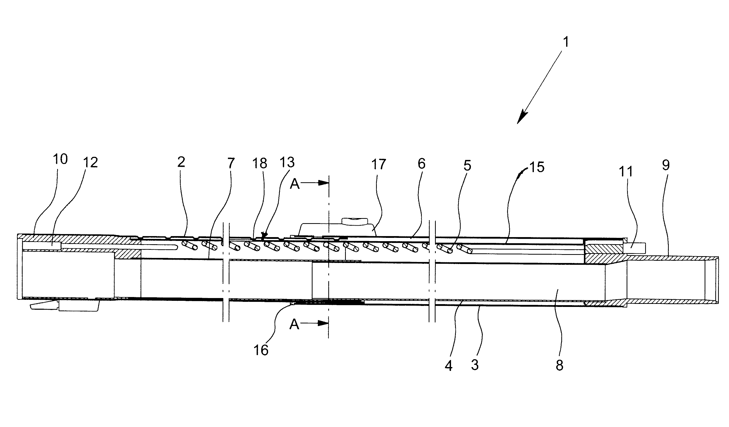
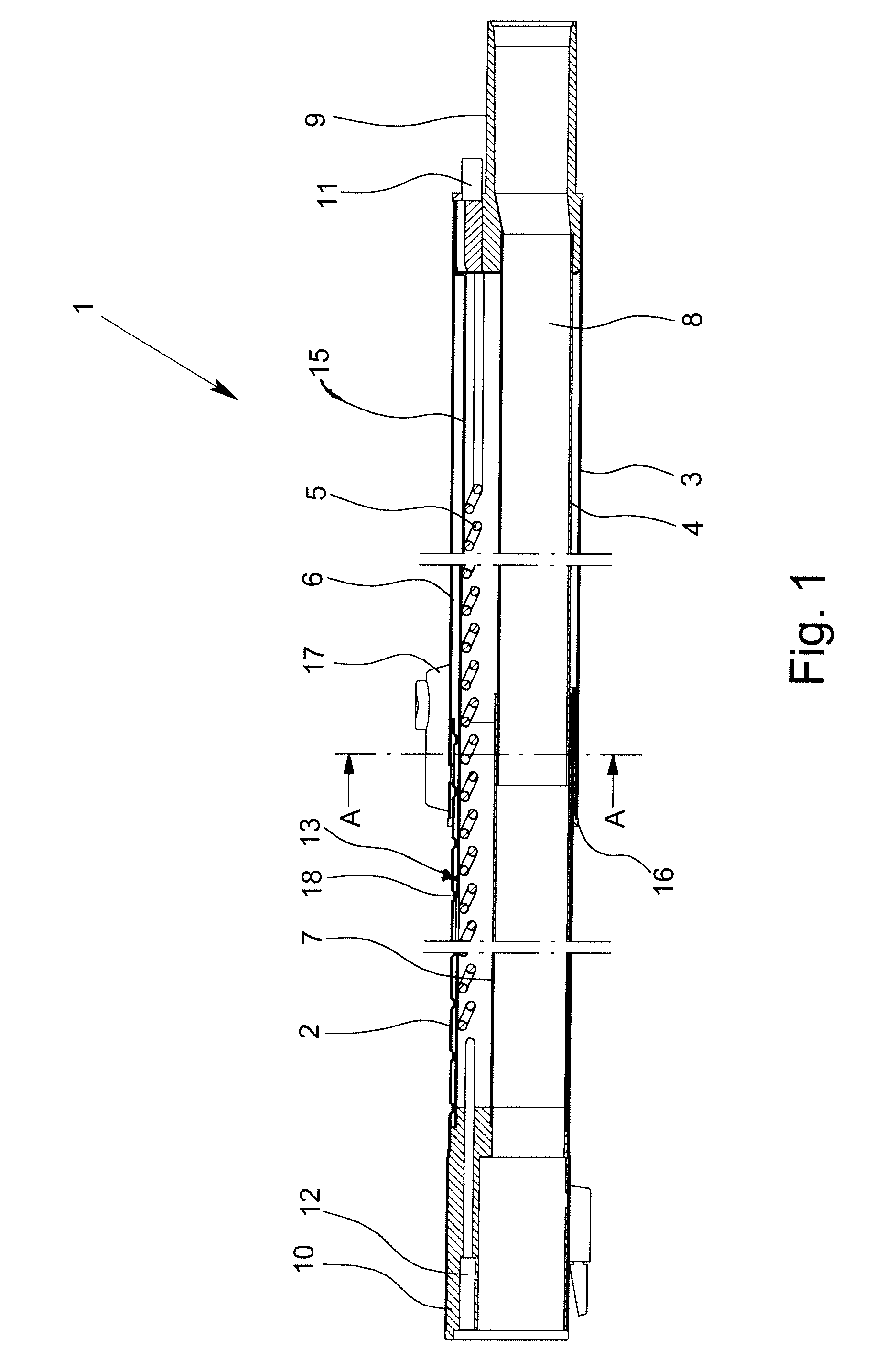
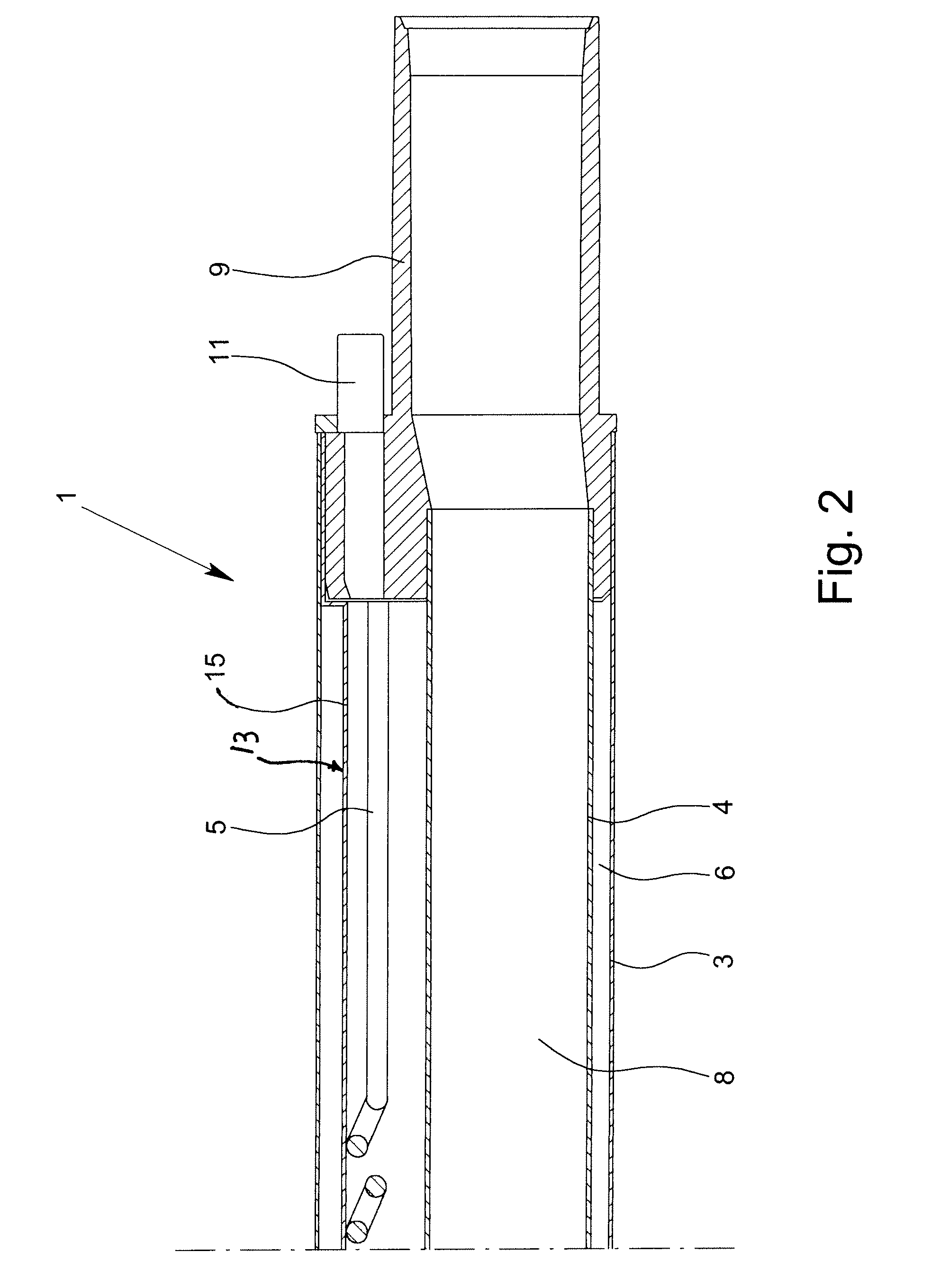
[0030]FIG. 1 shows a telescoping tube system 1 for a vacuum cleaner, with an inner jacket tube 2, an outer jacket tube 3, an inner suction tube 4 and a cable 5. The inner jacket tube 2 has a smaller cross section than the outer jacket tube 3 so that the inner jacket tube 2 and the outer jacket tube 3 form a telescoping jacket channel 6. The jacket channel 6 surrounds the inner suction tube 4 and the cable 5, the cable 5 being guided inward of the jacket channel 6 and outside the inner suction tube 4. The inner suction tube 4 together with an outer suction tube 7 forms an essentially closed suction channel 8. The suction channel 8 runs off-center with respect to the surrounding jacket channel 6.

[0031]Both the jacket channel 6 and also the suction channel 8 can be telescoped with respect to their length since the outer jacket tube 3 can be moved relative to the inner jacket tube 2, and the outer suction tube 7 relative to the inner suction tube 4. In the exemplary embodiment shown in ...


PUM


Abstract

A telescoping tube system for a vacuum cleaner, with an inner jacket tube, an outer jacket tube, an inner suction tube and a cable, the inner jacket tube having a smaller cross section than the outer jacket tube so that the inner jacket tube and the outer jacket tube form a telescoping jacket channel, the inner suction tube being located inside of the jacket channel, and the cable being guided within the jacket channel and outside of the inner suction tube. In the telescoping tube system, losses of suction force by the intake of secondary air are reduced to a minimum and reliable cable routing is ensured by there being an outer suction tube, the outer suction tube and the inner suction tube forming an essentially closed suction channel within the jacket channel.

Description

BACKGROUND OF THE INVENTION[0001]1. Field of the Invention[0002]The invention relates to a telescoping tube system for a vacuum cleaner, with an inner jacket tube, an outer jacket tube, an inner suction tube and a cable, the inner jacket tube having a smaller cross section than the outer jacket tube so that the inner jacket tube and the outer jacket tube form a telescoping jacket channel, the inner suction tube being located in the jacket channel, and the cable being guided within the jacket channel and outside the inner suction tube.[0003]2. Description of Related Art[0004]In the prior art telescoping tube systems are known in which the electric cable is guided along the tube system with a closed cable channel within the suction channel. Both the suction channel and also the cable channel can be telescoped and are connected to one another such that they have essentially the same length. The cable channel completely surrounds the cable and protects it against dirt and damage by part...

Claims


Application Information

Patent Timeline
Patent Type & Authority Patents(United States)
IPC IPC(8): A47L9/24
CPCA47L9/244A47L9/246
Inventor CORDES, MARTINCORDES, STEPHAN
Owner FISCHER ROHRTECHN
Why Eureka
Try Eureka