Connector for coaxial cable having rotational joint between insulator member and connector housing and associated methods

a technology of coaxial cable and connector housing, which is applied in the direction of coupling device connection, flexible/turnable line connector, coupling device details, etc., can solve the problems of degrading the electrical contact between the inner conductor and the center contact, loose metal chips may fall off the inner conductor, and the diameter of the inner conductor may be reduced, so as to achieve the effect of convenient installation

Active Publication Date: 2012-06-26
COMMSCOPE TECH LLC
View PDF22 Cites 48 Cited by
  • Summary
  • Abstract
  • Description
  • Claims
  • Application Information

AI Technical Summary

Benefits of technology

[0010]This and other objects, features, and advantages in accordance with the present invention are provided by a connector to be attached to a coaxial cable comprising an inner conductor, an outer conductor, and a dielectric therebetween. The connector may include a connector housing having a cylindrical shape to be coupled to the outer conductor, and an insulator member having a central opening therein. The insulator member may be rotatably received within the connector hosing to define a rotational joint therewith. A center contact may have a shaft portion securely received within the central opening of the insulator member. In addition, the center contact may have an open end portion extending rearwardly from the shaft portion to securely receive the inner conductor therein. This design advantageously helps to reduce or eliminate rotation of the center contact about the inner conductor when the connector housing and back nut are rotatably engaged during connector installation. This helps to reduce damage to the inner conductor caused by rotation of the center contact thereabout, particularly to coaxial cables with aluminum inner conductors. When the inner conductor undergoes scraping caused by the rotation of the center contact thereabout, the diameter of the inner conductor may be reduced and the surface may be uneven, thereby degrading the electrical contact between the inner conductor and the center contact. In addition, loose metal chips may flake off the inner conductor. The presence of metal chips between the inner conductor and the center contact also worsens the electrical contact therebetween, increasing intermodulation distortion.
[0011]There may be cooperating first and second rotation locking features defined in the center contact and insulator member to prevent relative rotation therebetween. In addition, the connector may include a back nut to be coupled to the connector housing and to capture the outer conductor therebetween. The connector housing may define a radially outer ramp to receive the outer conductor thereagainst. A compressible ring may compressibly clamp the outer conductor against the ramp as the connector housing and the back nut are engaged. This compressible ring advantageously provides secure mechanical and electrical connections between the outer conductor and the connector housing. Furthermore, this maintains a sufficient clamping force on the outer conductor opposite the radially outer ramp even if the size and / or shape of the outer conductor changes due to thermal expansion or aluminum creep.
[0012]Further, the radially outer ramp may be angled such as to flare an end of the outer conductor as the coaxial cable is inserted into the connector housing. This helpfully reduces the amount of preparation performed on an end of the coaxial cable before installation of the connector thereon.

Problems solved by technology

When the inner conductor undergoes scraping caused by the rotation of the center contact thereabout, the diameter of the inner conductor may be reduced and the surface may be uneven, thereby degrading the electrical contact between the inner conductor and the center contact.
In addition, loose metal chips may flake off the inner conductor.
The presence of metal chips between the inner conductor and the center contact also worsens the electrical contact therebetween, increasing intermodulation distortion.

Method used


Image

  • Connector for coaxial cable having rotational joint between insulator member and connector housing and associated methods
  • Connector for coaxial cable having rotational joint between insulator member and connector housing and associated methods
  • Connector for coaxial cable having rotational joint between insulator member and connector housing and associated methods

Examples


Embodiment Construction

[0034]The present invention will now be described more fully hereinafter with reference to the accompanying drawings, in which preferred embodiments of the invention are shown. This invention may, however, be embodied in many different forms and should not be construed as limited to the embodiments set forth herein. Rather, these embodiments are provided so that this disclosure will be thorough and complete, and will fully convey the scope of the invention to those skilled in the art. Like numbers refer to like elements throughout, and prime and multiple prime notation are used to indicate similar elements in alternative embodiments.

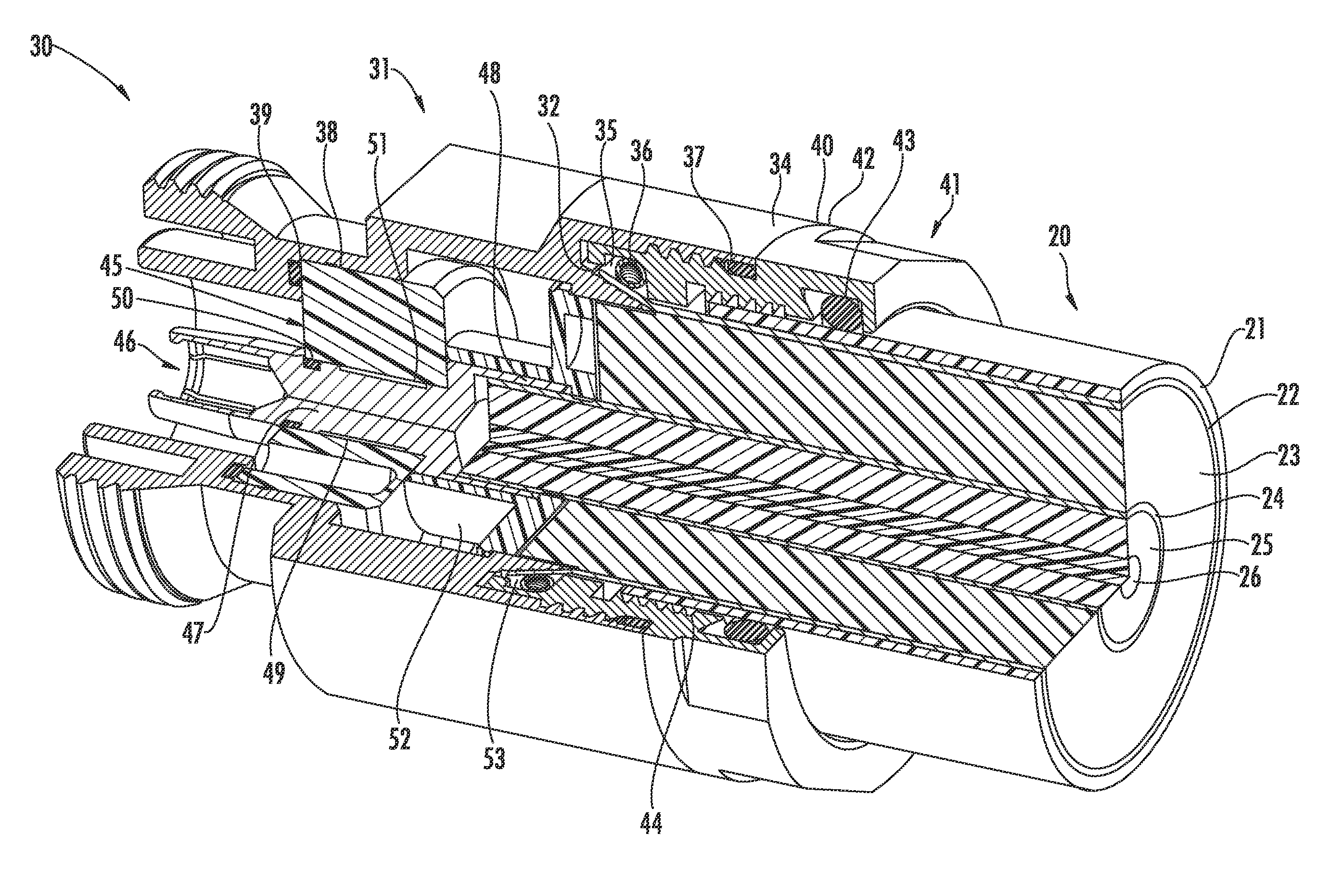
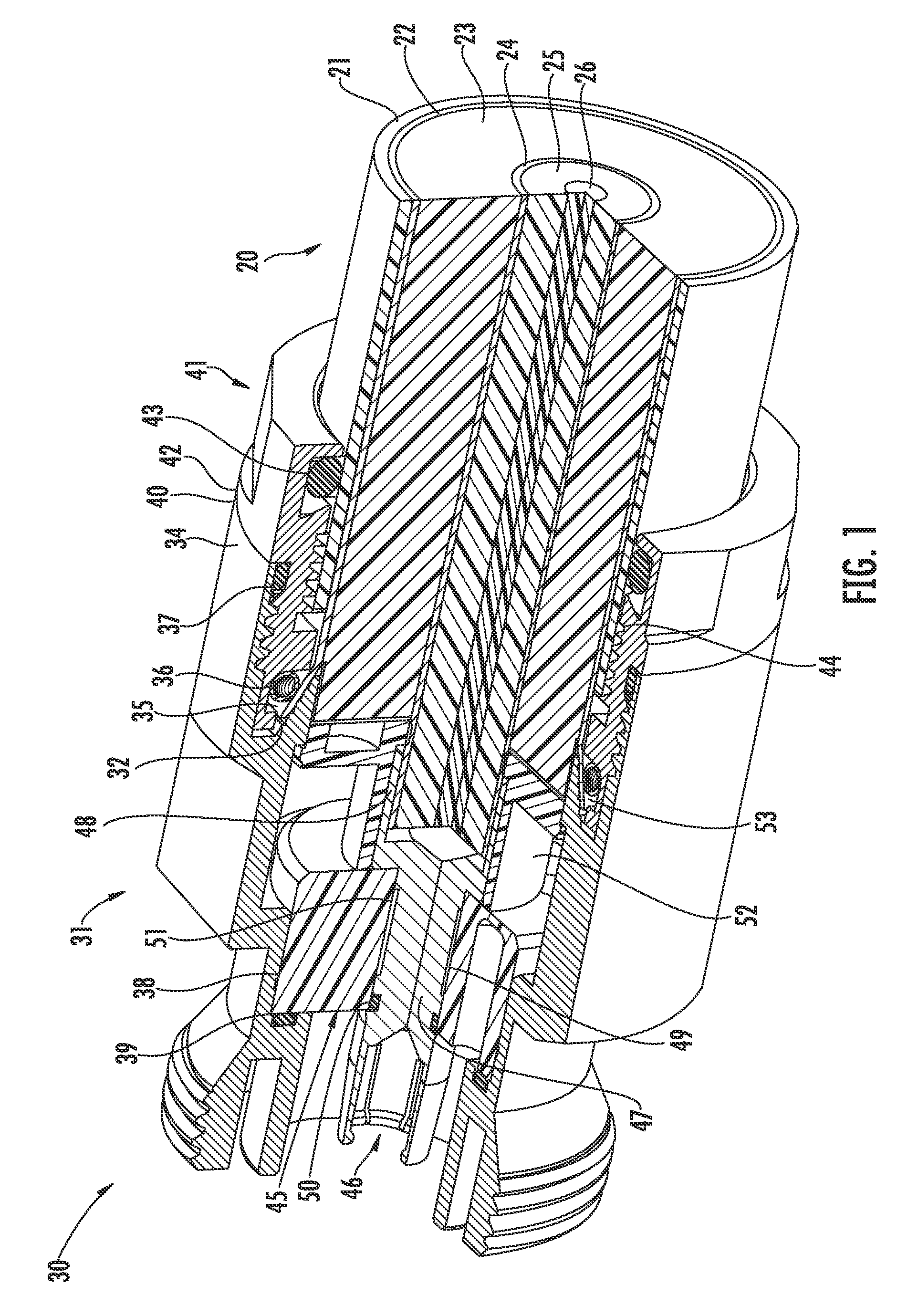
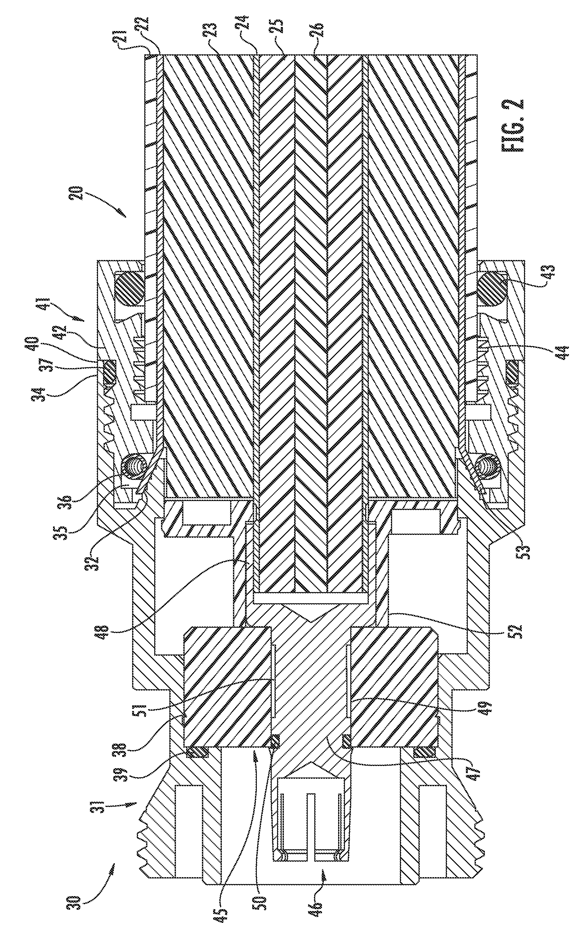
[0035]Referring initially to FIGS. 1-2, a connector 30 attached to a coaxial cable 20 is now described. The coaxial cable 20 comprises an inner conductor 24, an outer conductor 21, and a dielectric 23 therebetween. The inner conductor 24 (which may comprise aluminum, copper, copper clad aluminum, or other suitable type of metal) is a hollow inner conduct...


PUM

PropertyMeasurementUnit
dielectricaaaaaaaaaa
cylindrical shapeaaaaaaaaaa
electrically conductiveaaaaaaaaaa

Abstract

A connector is to be attached to a coaxial cable. The connector includes a connector housing having a cylindrical shape to be coupled to the outer conductor. An insulator member has a central opening therein and is rotatably received within the connector housing to define a rotational joint therewith. A center contact has a shaft portion securely received within the central opening of the insulator member and an open end portion extending rearwardly from the shaft portion to securely receive the inner conductor therein.

Description

FIELD OF THE INVENTION[0001]The present invention relates to the field of connectors for cables, and, more particularly, to connectors for coaxial cables and related methods.BACKGROUND OF THE INVENTION[0002]Coaxial cables are widely used to carry high frequency electrical signals. Coaxial cables enjoy a relatively high bandwidth, low signal losses, are mechanically robust, and are relatively low cost. One particularly advantageous use of a coaxial cable is for connecting electronics at a cellular or wireless base station to an antenna mounted at the top of a nearby antenna tower. For example, the transmitter located in an equipment shelter may be connected to a transmit antenna supported by the antenna tower. Similarly, the receiver is also connected to its associated receiver antenna by a coaxial cable path.[0003]A typical installation includes a relatively large diameter coaxial cable extending between the equipment shelter and the top of the antenna tower to thereby reduce signal...

Claims


Application Information

Patent Timeline
Patent Type & Authority Patents(United States)
IPC IPC(8): H01R9/05
CPCH01R13/565H01R35/00H01R9/0521Y10T29/49208H01R2103/00H01R24/40H01R4/48
Inventor ISLAM, NAHID
Owner COMMSCOPE TECH LLC
Why Eureka
Try Eureka