Shaft for golf club

a golf club and shaft technology, applied in the field of shafts for golf clubs, can solve the problems of many players who are bothered by a sense of discomfort, and cannot reduce the deformation amount of the shaft, so as to improve the flying distance, suppress the increase in the weight of the shaft, and improve the effect of swing speed

Active Publication Date: 2012-06-26
MRC COMPOSITE PRODS
View PDF22 Cites 9 Cited by
  • Summary
  • Abstract
  • Description
  • Claims
  • Application Information

AI Technical Summary

Benefits of technology

[0023]According to the shaft for a golf club of the present invention, there is provided a golf club in which even though the length of the shaft is extended, since the crush deformation amount is reduced and the increase in weight of the shaft is suppressed, swing speed can be increased to improve the flying distance when hitting a ball, and the controllability can be enhanced to reduce variations in directivity of the hit ball.

Problems solved by technology

Consequently, it is not possible to sufficiently reduce the deformation amount of the shaft.
Further, there is a problem in that since the grip is thicker than a conventional golf club, there are many players who are bothered by a sense of discomfort.

Method used


Image

  • Shaft for golf club
  • Shaft for golf club
  • Shaft for golf club

Examples


example 1

[0087]

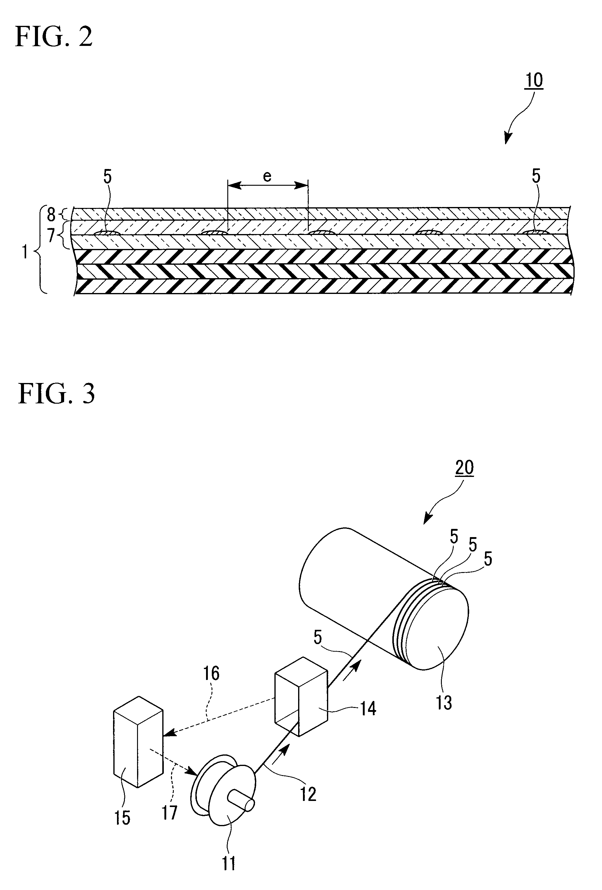
[0088]By using the drum winding device 20 shown in FIG. 3, a prepreg with the metal wires interposed therebetween was manufactured (see a drum winding method disclosed in Japanese Unexamined Patent Application, First Publication No. 2001-341126). The drum winding device 20 includes an unwinding bobbin 11 rotating and drawing out the metal wire 5 and a drum 13 for winding the metal wire 5 drawn out from the unwinding bobbin 11. Further, the drum winding device 20 includes a detector 14, disposed between the unwinding bobbin 11 and the drum 13, for detecting tension applied to the metal wire 5, and a brake 15 for controlling the rotational speed of the unwinding bobbin 11 based on measured data of the tension detected by the detector 14. In addition, the drum winding device 20 includes a signal line 16 for transferring the measured data of the tension detected by the detector 14 to the brake 15, and a signal line 17 connecting the brake 15 and the unwinding bobbin 11 and transfe...


PUM


Abstract

A shaft for a golf club comprises a plurality of fiber-reinforced resin layers. A plurality of circumferentially oriented metal wires are provided at intervals of 1 mm to 4 mm in an axial direction of the shaft having a length in an axial direction of more than 100 mm and less than 300 mm and being centered at a position of 3.25×102 mm from a larger-diameter end of the shaft.

Description

TECHNICAL FIELD[0001]The present invention relates to a shaft for a golf club.[0002]The present application claims priority from Japanese Patent Application No. 2007-234023, filed on Sep. 10, 2007, the contents of which are hereby incorporated by reference into this application.BACKGROUND ART[0003]In order to improve the flying distance of a hit ball in golf, the use of a long-sized golf club which has a long shaft for golf club is effective. Hereinafter, the “shaft for golf club” is referred to as a “shaft”. If the long-sized golf club is used, the head speed is increased at the time of the swing of the golf club; therefore, the flying distance is extended.[0004]However, if a long-sized golf club is used, since the position the ball is hit in is distant from the grip when compared with a golf club of a common length, there is a problem in that the possibility of miss-hitting the ball increases.[0005]Recently, for the purposes of solving the miss-hitting by the long-sized golf club,...

Claims


Application Information

Patent Timeline
Patent Type & Authority Patents(United States)
IPC IPC(8): A63B53/10A63B53/12A63B102/32
CPCA63B53/10A63B59/0014A63B2209/02A63B2209/023A63B60/10A63B60/06A63B60/08A63B53/12A63B60/42
Inventor KANEKO, TAKASHISHIGA, KOUJIATSUMI, TETSUYAIBUKI, TSUTOMU
Owner MRC COMPOSITE PRODS
Why Eureka
Try Eureka