
Rotation mechanism and robot using the same

a technology of rotating mechanism and rotating platform, which is applied in the direction of mechanical control device, process and machine control, instruments, etc., can solve the problems of limited movement range of control arms and movable platform

Inactive Publication Date: 2012-07-03
SHENZHENSHI YUZHAN PRECISION TECH CO LTD +1
View PDF7 Cites 97 Cited by
  • Summary
  • Abstract
  • Description
  • Claims
  • Application Information

AI Technical Summary

Benefits of technology

The present patent is about a rotation mechanism and a robot applying it. The technical effect of the patent is to overcome the limitations of current parallel robots by providing a rotation mechanism that can swing and a robot applying it. This allows for greater flexibility and dynamic movements in the robot.

Problems solved by technology

However, movement range of the control arms and the movable platform are limited by a length of the shaft.

Method used


Image

  • Rotation mechanism and robot using the same
  • Rotation mechanism and robot using the same
  • Rotation mechanism and robot using the same

Examples


Embodiment Construction

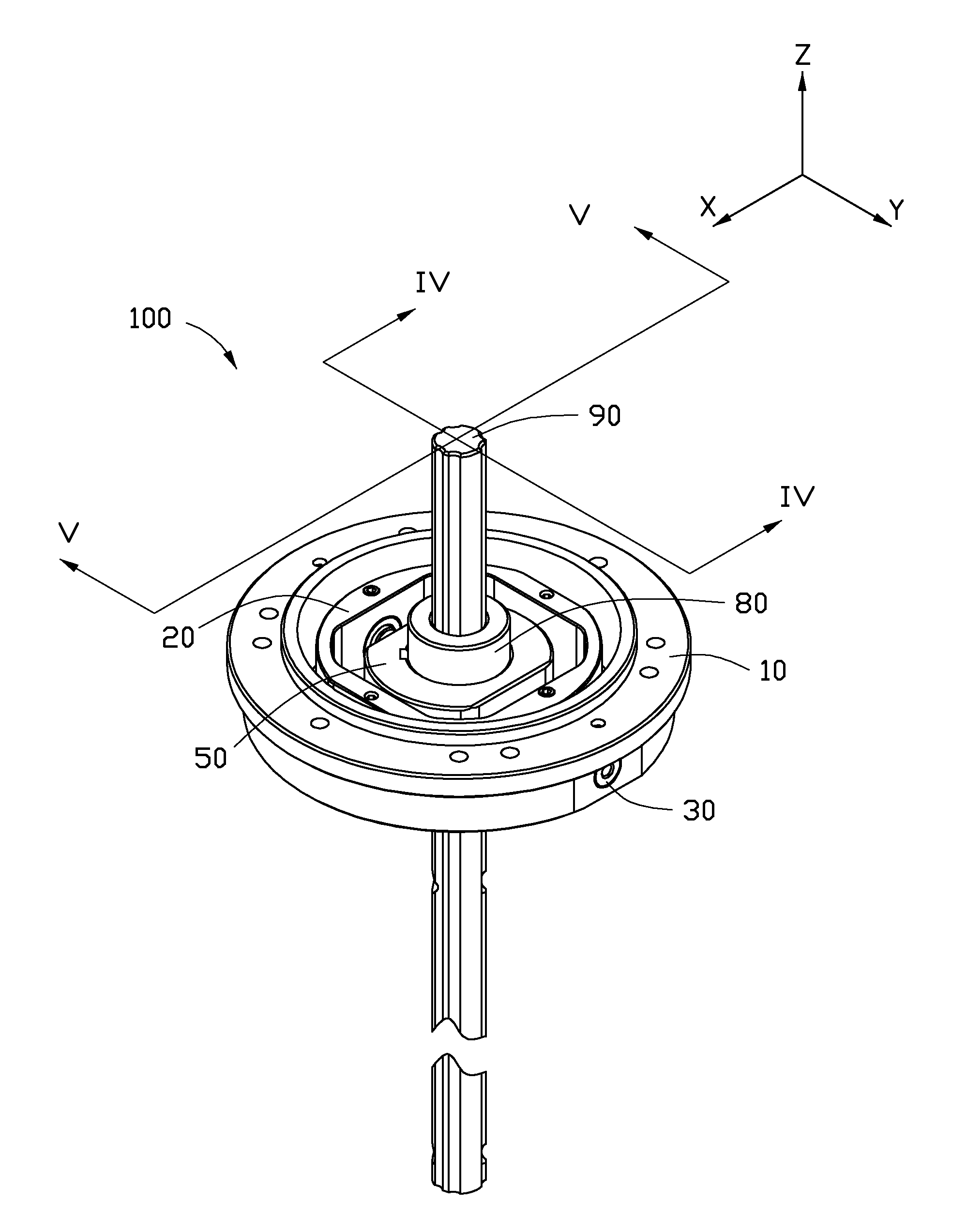
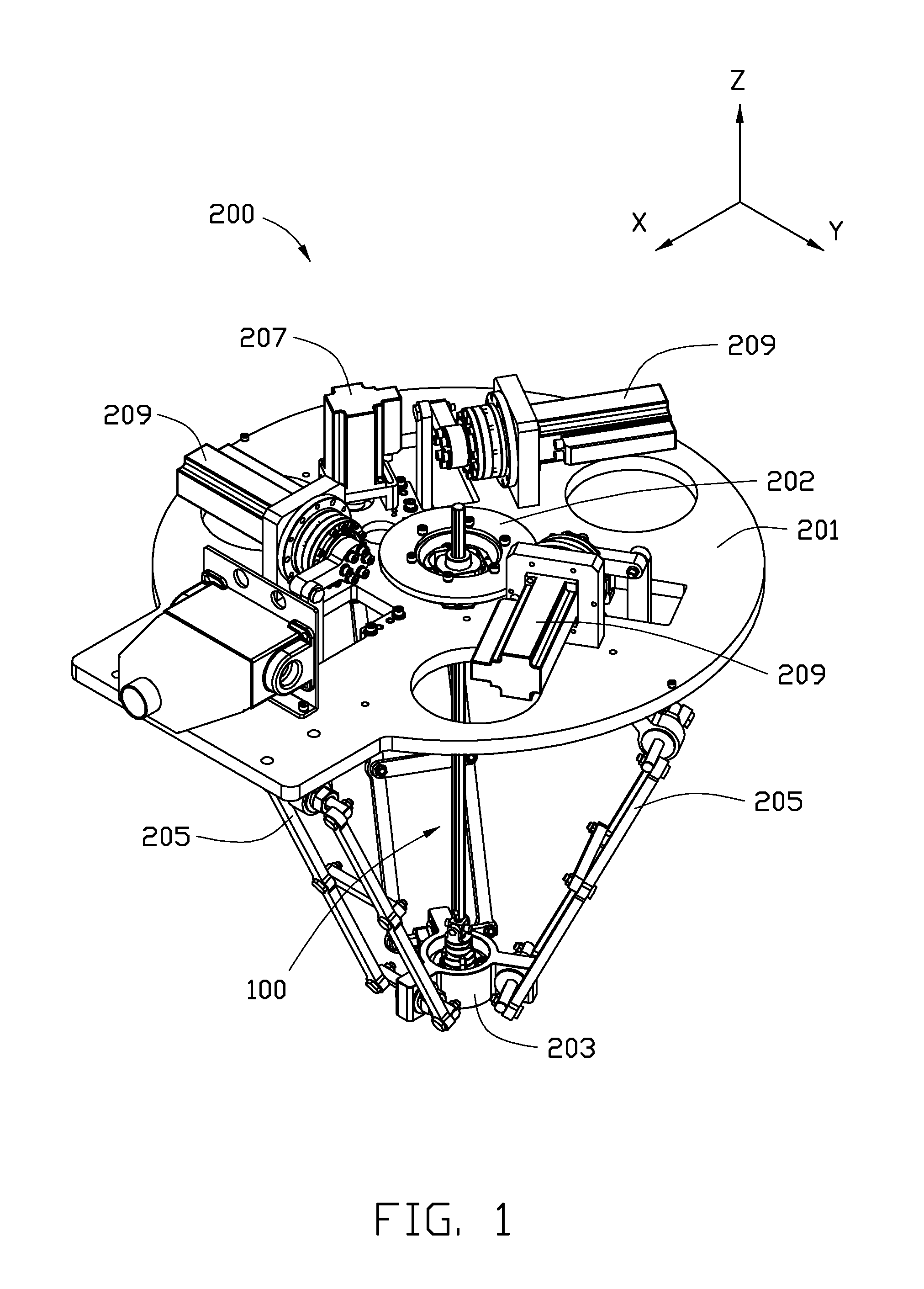
[0013]Referring to FIG. 1, an embodiment of a robot 200 is shown. The robot 200 is a parallel robot with four degrees of freedom. The robot 200 includes a base 201, a movable platform 203, three control arms 205 rotatably connecting the base 201 with the movable platform 203, and a rotation mechanism 100. The base 201 further includes a first actuator 207 and a gear 202. The first actuator 207 and the gear 202 are mounted on the base 201. The gear 202 can be driven by the first actuator 207. In the illustrated embodiment, the first actuator 207 is a servo motor.

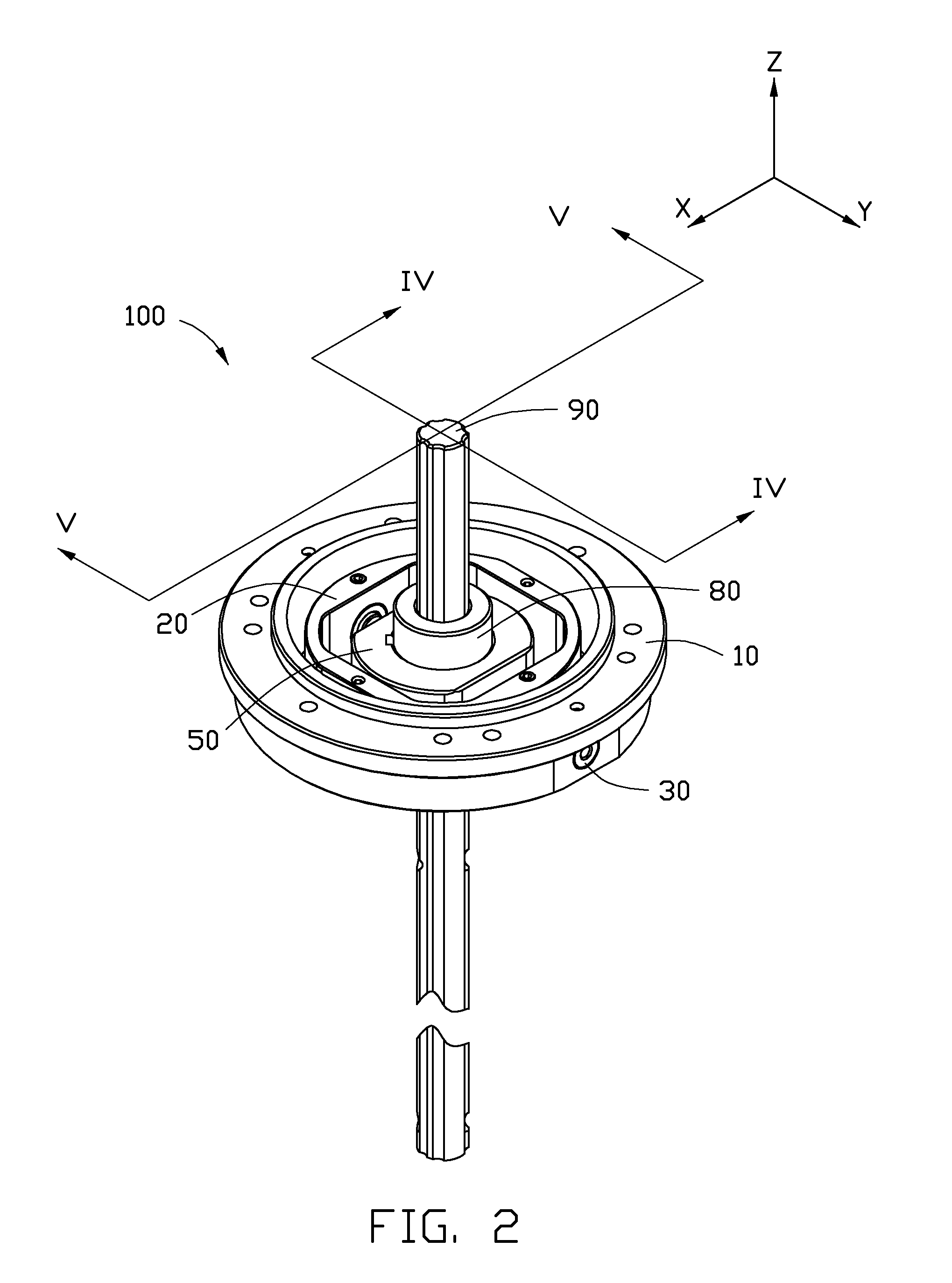
[0014]The rotation mechanism 100 includes a flange 10 fixed to the gear 202 and a shaft 90 extending through the flange 10; and the rotation mechanism 100 has one end movably connected to the movable platform 203. The robot 200 further comprises three second actuators 209 connected to the control arms 205, respectively, to drive the control arms 205. During operation, the second actuators 209 drive the control arms 205 to mak...


PUM


Abstract

A rotation mechanism includes a flange, a shaft, a first swing member, and a second swing member. The shaft extends along a first axis. The first swing member is rotatably connected to and received in the flange around a second axis substantially perpendicular to the first axis. The second swing member is rotatably connected to and received in the first swing member around a third axis substantially perpendicular to the first axis and the second axis. The shaft extends through the flange, the first swing member, and the second swing member. The shaft is non-rotatably and slidably received in the second swing member. A robot using the rotation mechanism is also provided.

Description

BACKGROUND[0001]1. Technical Field[0002]The present disclosure generally relates to rotation mechanisms, and particularly, to a rotation mechanism capable of swinging and a robot applying the rotation mechanism.[0003]2. Description of Related Art[0004]Parallel robots have advantages of stability, load-bearing, favorable weight to load ratio, dynamic characteristics, and others. As parallel robots and series robots cooperate, they may be used in many fields. Delta robots are typically parallel robots with three degrees of freedom, with simpler, more compact structure and favorable dynamic characteristics.[0005]A typical delta robot includes a base, a movable platform, a shaft and three control arms. The shaft and the control arms connect the movable platform and the base. Opposite ends of the shaft are ball-pivoted on the base and the movable platform, respectively. Opposite ends of each control arm are pivoted to the base and movable platform. During use, an electric motor drives th...

Claims


Application Information

Patent Timeline
Patent Type & Authority Patents(United States)
IPC IPC(8): B25J17/00B25J17/02B25J18/00
CPCB25J17/0266B25J9/0051Y10T74/20305Y10T74/20329
Inventor FENG, YONG
Owner SHENZHENSHI YUZHAN PRECISION TECH CO LTD
Learn More