Pneumatic tire

a pneumatic tire and tire body technology, applied in the field of pneumatic tires, can solve the problems of insufficient block rigidity of pneumatic tires for use on icy and snowy roads, difficulty in achieving pneumatic tires, and insufficient wear resistance of pneumatic tires for dry road surfaces,

Active Publication Date: 2012-07-03
THE YOKOHAMA RUBBER CO LTD
View PDF15 Cites 6 Cited by
  • Summary
  • Abstract
  • Description
  • Claims
  • Application Information

AI Technical Summary

Benefits of technology

[0005]An object of the present invention is to provide a pneumatic tire having improved driving stability and wear resistance on dry road surfaces as well as an improved running performance on snow.
[0007]In the present invention, the tread portion is partitioned into the plurality of lines of land sections by the first, second, and third main grooves. The width of the first land section closer to the center of the vehicle is set greater than the width of the second land section farther from the center of the vehicle, and the inclined grooves each having a relatively large length are disposed in the first land section. This arrangement makes it possible to optimize the block rigidity, and to sufficiently secure the driving stability and wear resistance on dry road surfaces. Moreover, the inclined grooves disposed in the first land section make it possible to improve the running performance, such as driving stability and turnability, on snow.
[0008]In the present invention, the following structure is preferably employed for achieving a good balance between the running performance on snow as well as the driving stability and wear resistance on dry road surfaces. Specifically, each inclined groove may communicate with three of the lug grooves, so that four types of blocks defined by the three lug grooves and the inclined groove are disposed as a repeating unit in the first land section. In addition, a plurality of blocks defined by the plurality of lug grooves may be disposed in the second land section. Moreover, a surface area Sa of a block A located in a region, closer to the center of the vehicle and closer to the other end of the inclined groove, of the first land section; a surface area Sb of a block B located in a region, closer to the center of the vehicle and closer to the one end of the inclined groove, of the first land section; a surface area Sc of a block C located in a region, farther from the center of the vehicle and closer to the other end of the inclined groove, of the first land section; a surface area Sd of a block D located in a region, farther from the center of the vehicle and closer to the one end of the inclined groove, of the first land section; a surface area Se of a block E, adjacent to the block C, in the second land section; and a surface area Sf of a block F, adjacent to the block D, in the second land section, may be set to satisfy the following relations. It goes without saying that the surface area mentioned here is the surface area of a ground-contacting surface.Sa=Se×92% to 100%,Sb=Sf×110% to 118%,Sc=Se×110% to 115%,andSd=Sf×95% to 100%.
[0010]Further, it is also effective to employ the following structure for achieving a good balance between the running performance on snow as well as the driving stability and wear resistance on dry road surfaces. Specifically, the width of the first land section may be set at 50% to 70% of a tread contact half-width. The width of the second land section may be set at 15% to 35% of the tread contact half-width. A groove width y1 of a part of each lug groove, farther from the center of the vehicle, in the second land section may be set to be 40% to 50% of a groove width y2 of a part thereof, closer to the center of the vehicle, in the second land section. An inclination angle of the inclined grooves to the tire circumferential direction may be set at 10° to 30°. A sum of groove widths of the first, second, and third main grooves, may be set at 15% to 35% of a tread contact width.
[0012]In the present invention, when forming a pneumatic tire for use on icy and snowy roads represented by a studless tire, a plurality of sipes each extending in the tire width direction are preferably provided in each of land sections including the first and second land sections. The present invention provides significant operational effects when being applied to a pneumatic tire for use on icy and snowy roads; however, it is also possible to apply the present invention to an all-season pneumatic tire.

Problems solved by technology

In general, it is difficult to achieve, in a pneumatic tire, both of the running performance on snow and the running performance on dry road surfaces.
However, such pneumatic tire for use on icy and snowy roads is insufficient in block rigidity because a soft tread rubber is employed in general.
For this reason, currently-available pneumatic tires for use on icy and snowy roads are not satisfactory in the driving stability and wear resistance on dry road surfaces.

Method used


Image

  • Pneumatic tire
  • Pneumatic tire
  • Pneumatic tire

Examples


examples

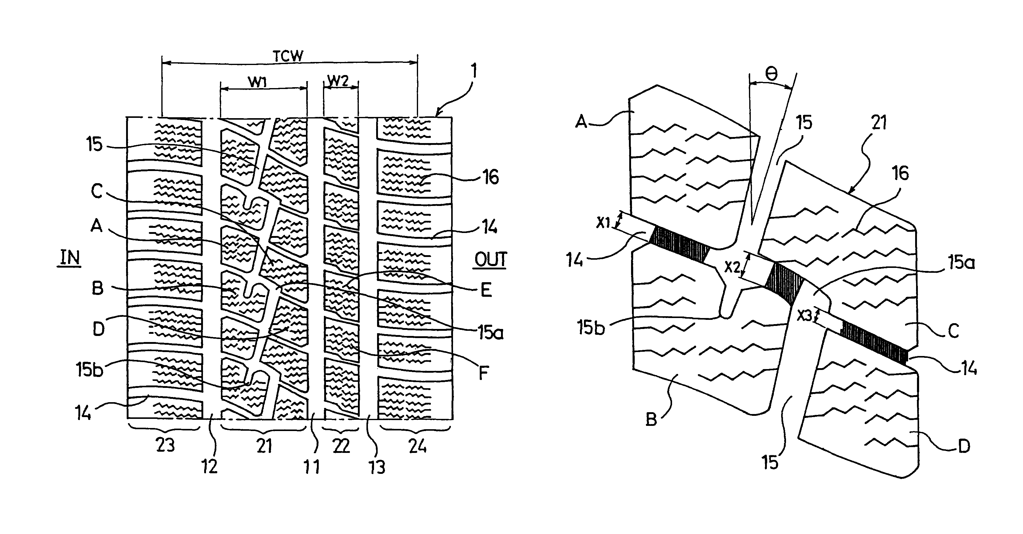
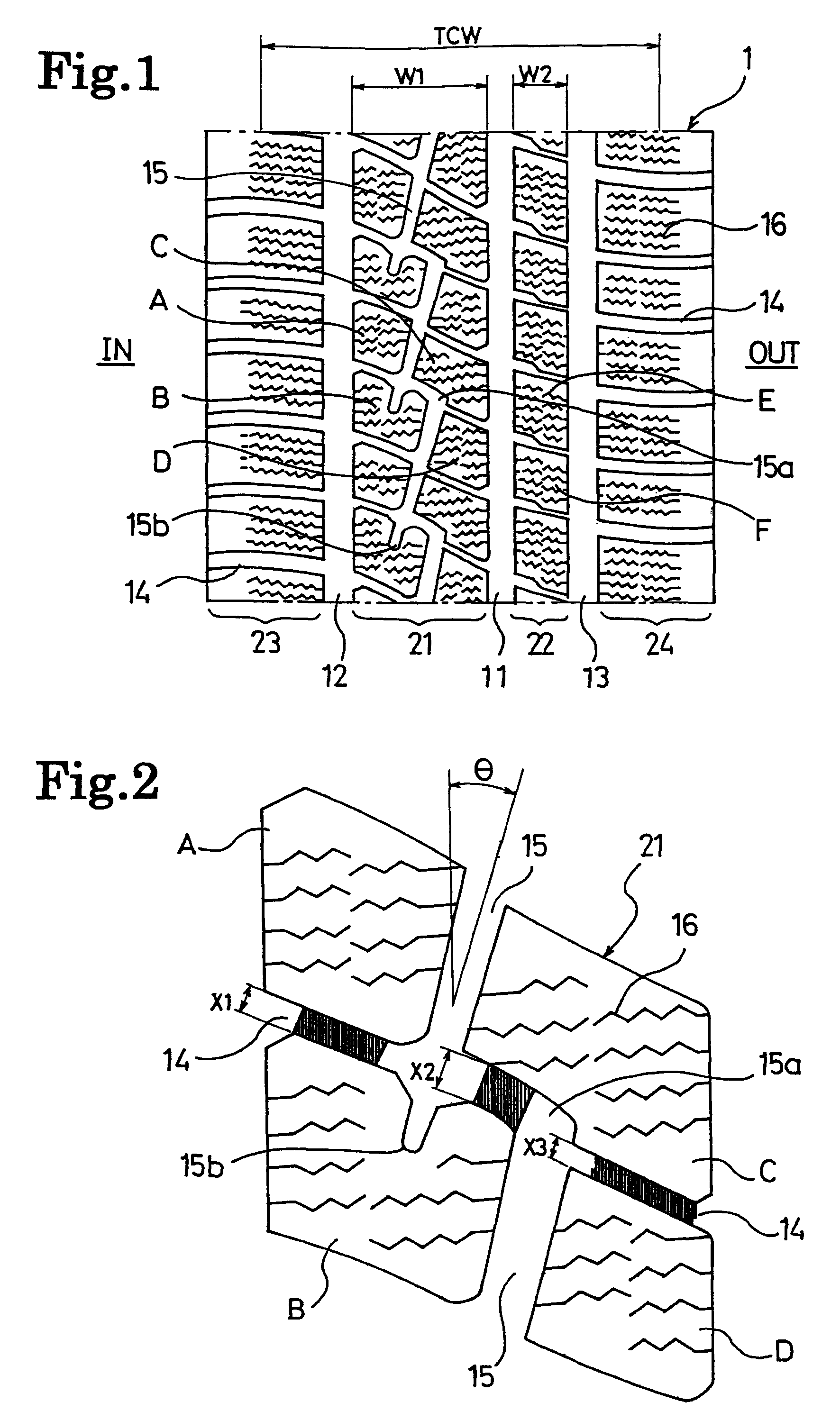
[0039]Pneumatic tires for use on icy and snowy roads of Conventional Example and Examples 1 to 3 were prepared. These tires had a tire size of 205 / 55R16 while their tread patterns were made different from one another.

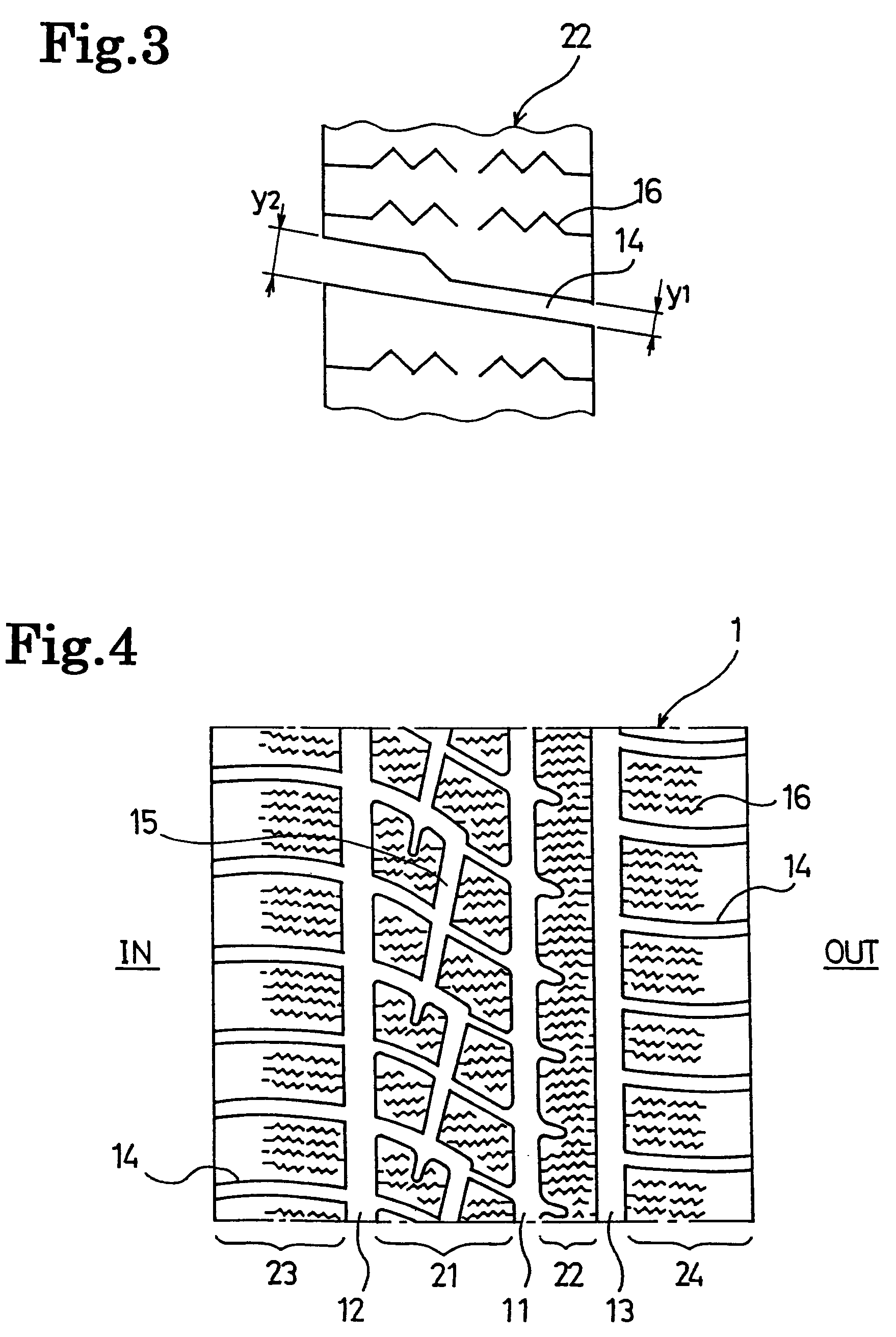
[0040]Conventional Example had a tread portion in which five main grooves each extending in the tire circumferential direction and multiple lug grooves each extending in the tire width direction were provided, so that a large number of rectangular blocks were defined by these main grooves and lug grooves. On the other hand, Example 1 had the tread pattern shown in FIG. 1, Example 2 has the tread pattern shown in FIG. 4, and Example 3 had the tread pattern shown in FIG. 5. Each of Examples 1 to 3 had the following configuration. The width of the first land section was set at 56% of the tread contact half-width, while the width of the second land section was set at 27% of the tread contact half-width. The inclination angle of the inclined grooves to the tire circumferenti...


PUM


Abstract

A pneumatic tire having improved driving stability and wear resistance on dry road surfaces and improved running performance on snow. The pneumatic tire includes a tread portion provided with first, second and third main grooves extending in a tire circumferential direction and a plurality of lug grooves each extending from one shoulder side to the other shoulder side. A width of a first land section defined between the first and second main grooves is set greater than a width of a second land section defined between the first and third main grooves, a plurality of inclined grooves are provided in the first land section, where each inclined groove communicates with at least three of the lug grooves while being inclined to the tire circumferential direction, and one end of each inclined groove is open to one of the lug grooves while the other end thereof is terminated within a block.

Description

[0001]This application is a U.S. National Phase under 35 U.S.C. §371, of International Application No. PCT / JP2006 / 316986, filed Aug. 29, 2006.TECHNICAL FIELD[0002]The present invention relates to a pneumatic tire favorably used as a studless tire, and more specifically, relates to a pneumatic tire having improved driving stability and wear resistance on dry road surfaces as well as an improved running performance on snow.BACKGROUND ART[0003]In general, it is difficult to achieve, in a pneumatic tire, both of the running performance on snow and the running performance on dry road surfaces. For example, a pneumatic tire for use on icy and snowy roads has a tread portion in which multiple main grooves each extending in the tire circumferential direction and multiple lug grooves each extending in the tire width direction are provided, so that a large number of blocks are defined by these main grooves and lug grooves (see, for example, Patent Document 1). Such a pneumatic tire for use on...

Claims


Application Information

Patent Timeline
Patent Type & Authority Patents(United States)
IPC IPC(8): B60C11/11
CPCB60C11/0306B60C11/12B60C11/0304Y10S152/902B60C2011/1213B60C2011/0374
Inventor KISHIZOE, ISAMU
Owner THE YOKOHAMA RUBBER CO LTD
Why Eureka
Try Eureka