Booster cable

a technology of booster cable and connector, which is applied in the direction of connection, electrical apparatus, coupling device connection, etc., can solve the problems of insufficient clamping of the assisting terminal, difficult inserting of the clamping section of the connecting clip therein, etc., to reduce the opening amount reliably connect the connecting clip to the terminal, and increase the strength and rigidity of the clamping section.

Inactive Publication Date: 2012-07-03
SEIWA IND SEIWA KOGYO
View PDF7 Cites 2 Cited by
  • Summary
  • Abstract
  • Description
  • Claims
  • Application Information

AI Technical Summary

Benefits of technology

[0009]According to the structure above, since the clamping sections are formed to be wide, it is possible to increase strength and rigidity of the clamping sections without forming root portions of the clamping sections to be thick. Further, by setting the outer surfaces of the pair of clamping sections to be substantially parallel in the closed state, it is possible that the clamping sections are set to have approximately same thickness up to the root portions thereof. Thus, when inserting the clamping sections into a limited space, it is possible to prevent the root portions from interfering with the insertion such as the case of tapered clamping sections.
[0010]Additionally, as the clamping sections are formed to be wide, it is possible to clamp the flat terminal from the tip end part stably. This makes it possible to set the terminal to be flat to reduce the opening amount of the clamping sections required to clamp the terminal. As a result, even when the space where the terminal is provided is limited, it is possible that the clamping sections are inserted into the space to clamp the terminal and to reliably connect the connecting clip to the terminal.
[0011]Furthermore, according to the present embodiment, there is provided a booster cable in which a connecting clip is attached to both ends of a cable main body, in which the connecting clip is covered by an insulating cover, and so that a pair of clamping sections, exposed from the insulating cover, are inserted into a fuse box equipped in an engine room of an automobile to be capable of clamping a flat assisting terminal, protrudingly provided inside the fuse box and electrically connected to an auxiliary battery, from the tip end part of the assisting terminal, it is set that the clamping sections are wide and outer surfaces of the pair of clamping sections are substantially parallel in a closed state of the clamping sections. This structure is the same as that of the above described booster cable, and the clamping sections are capable of stably clamping the flat assisting terminal, protrudingly provided in a limited space of the fuse box, from the tip end part thereof. This makes it possible to reliably connect the booster cable to the assisting terminal, protrudingly provided inside the fuse box of the engine room and electrically connected to the auxiliary battery.

Problems solved by technology

However, since a space inside the fuse box is limited, the clamping sections of the connecting clip are difficult to be inserted therein and incapable of clamping the assisting terminal sufficiently.

Method used


Image

  • Booster cable
  • Booster cable
  • Booster cable

Examples


Embodiment Construction

[0024]Below, an embodiment of a booster cable according to the present invention will be described with reference to the accompanying drawings.

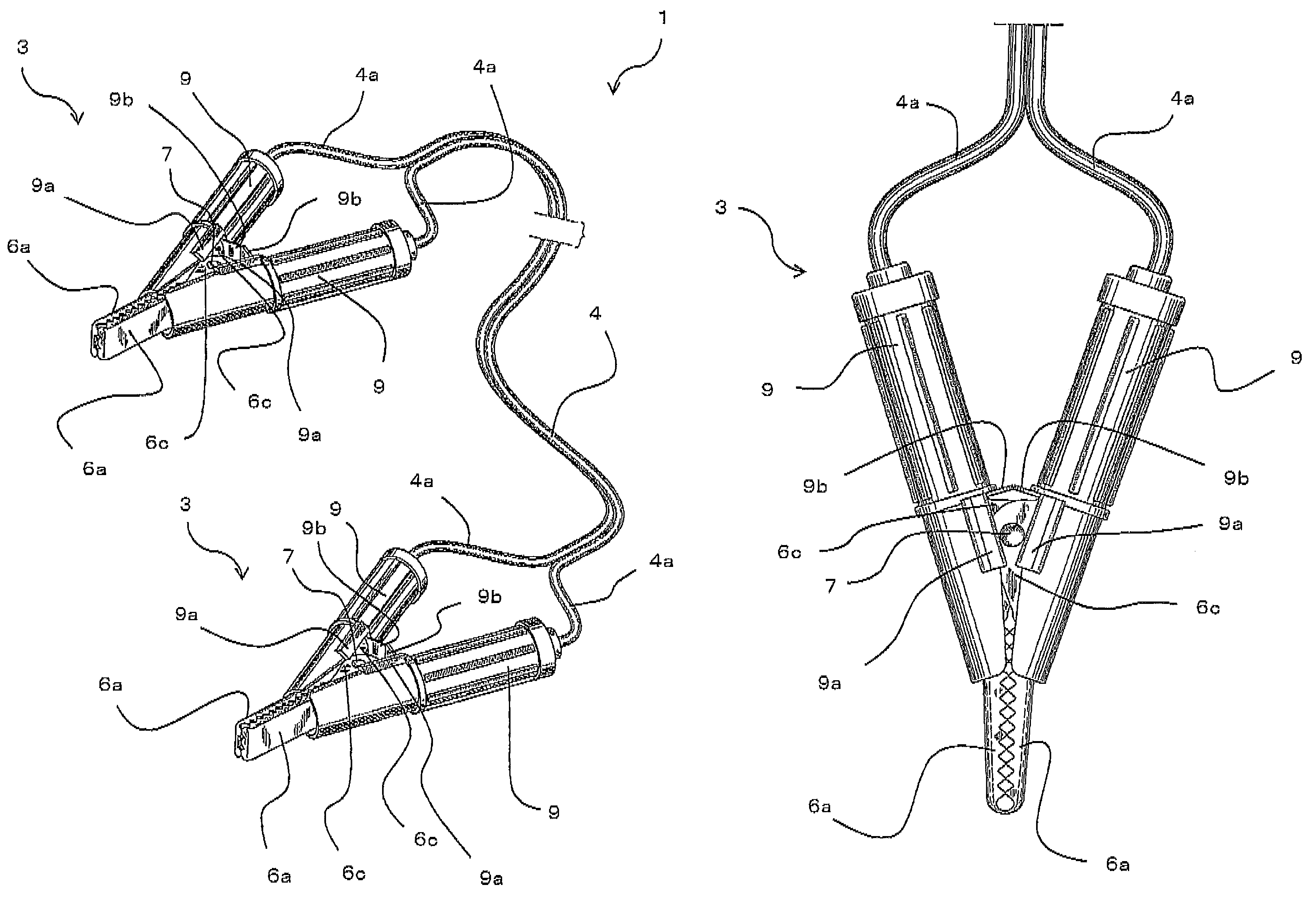
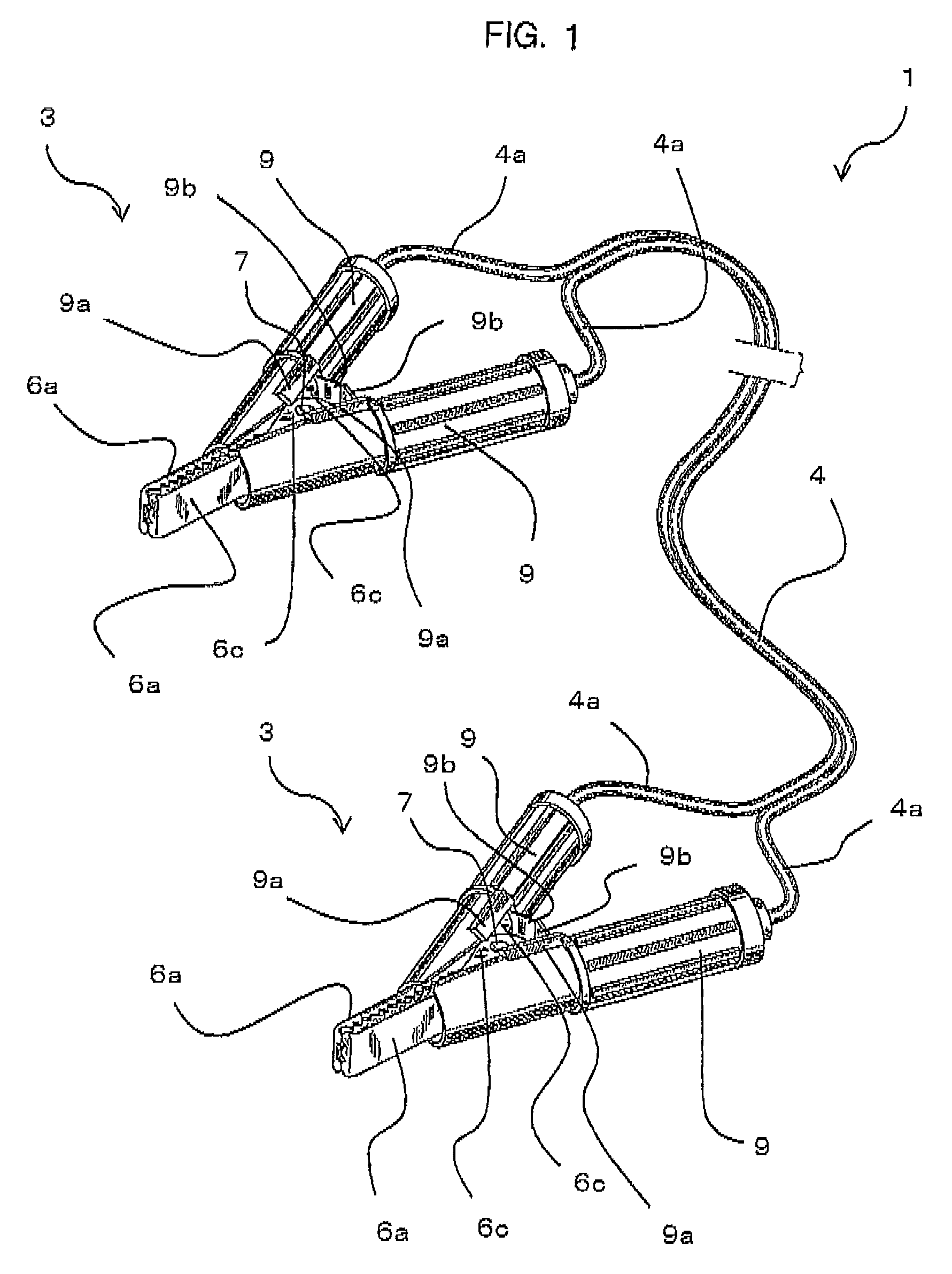
[0025]When an auxiliary battery 2 of an automobile is completely discharged, for example, a booster cable 1 is used for supplying electricity from a battery of an assisting car to the auxiliary battery 2. As shown in FIG. 1, the booster cable 1 has a structure in which connecting clips 3 are attached to both ends of a cable main body 4, and the connecting clips 3 at the both ends are connected to an assisting terminal 5 of the automobile and to an electrode terminal of a battery of the assisting car.

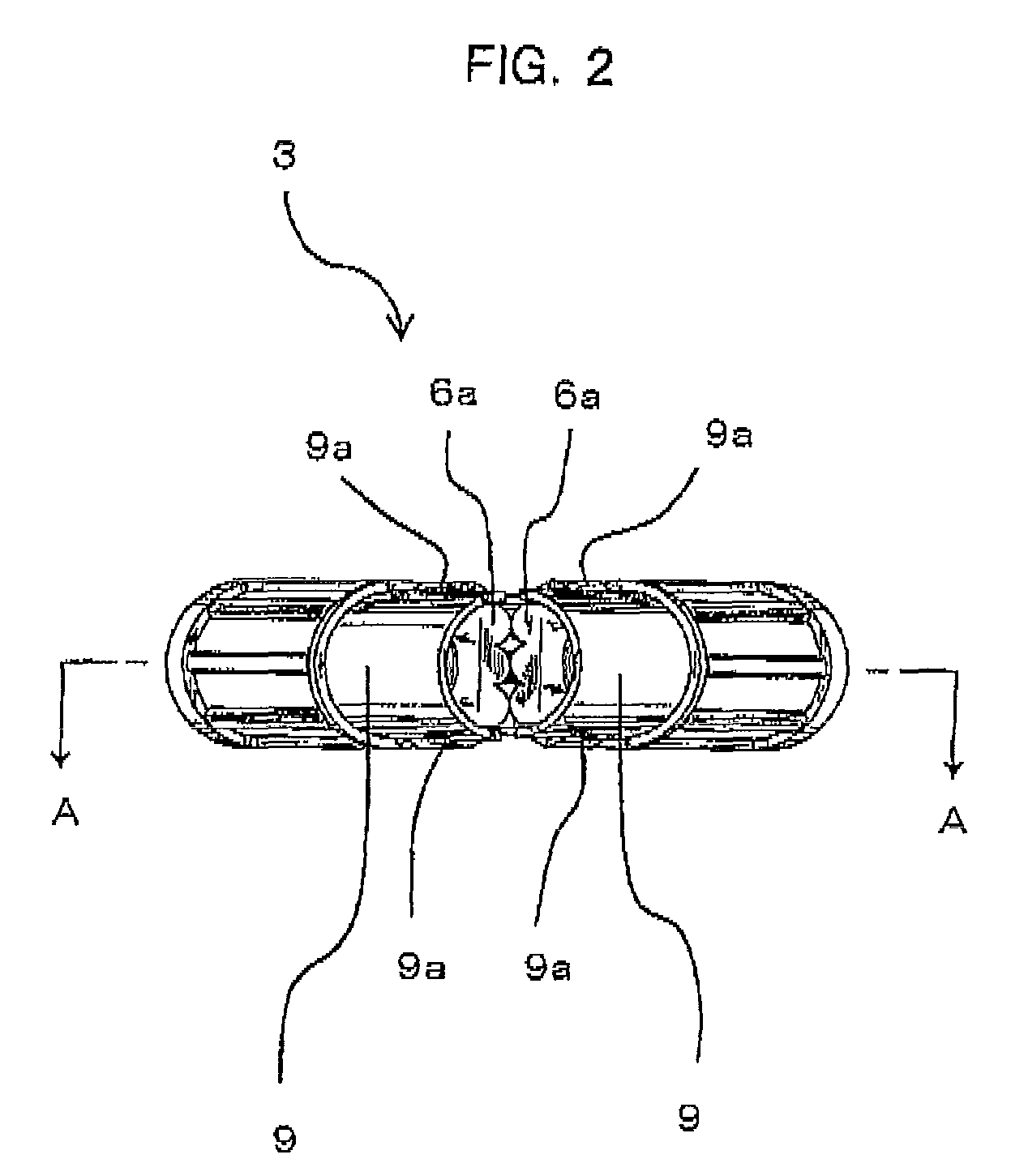
[0026]As shown in FIGS. 2 to 8, the connecting clip 3 has a structure in which a pair of metal members 6 that have clamping sections 6a on the tip end part, gripping sections 6b on the base end part, and center sections 6c therebetween are pivotally joined with each other. The connecting clip 3 is configured so that the pair of clamping sections 6...


PUM


Abstract

The present invention provides a booster cable capable of reliably being connected to a terminal that is provided in a limited space. Specifically, a connecting clip 3 is attached to both ends of a cable main body 4. Clamping sections 6a of the connecting clip 3 are set to be wide and outer surfaces of the pair of clamping sections 6a are set to be substantially in parallel in a closed state so that the clamping sections 6a are set to have approximately same thickness up to root portions. The root portions of the clamping sections 6a do not interfere so that the clamping sections 6a are able to be inserted into a limited space up to the root portions. It is thereby possible to sufficiently clamp and reliably connect the assisting terminal 5 that is provided in a limited space.

Description

BACKGROUND OF THE INVENTION[0001]1. Field of the Invention[0002]The present invention relates to a booster cable for connecting batteries, for instance, to supply electricity from one of the batteries to the other battery.[0003]2. Description of the Related Art[0004]Generally, when a battery mounted on a vehicle is completely discharged, electricity is supplied by connecting a battery of an assisting car to the discharged battery. For connecting the battery of the assisting car to the discharged battery, a booster cable is used.[0005]The booster cable has a structure in which connecting clips to be connected to electrode terminals are attached to both ends of a cable main body. The connecting clip has a structure in which a pair of metal members are pivotally joined with each other so that clamping sections on the tip end portion open and close to clamp the electrode terminal. The clamping sections of the connecting clip are formed into a tapered shape having a thick root portion an...

Claims


Application Information

Patent Timeline
Patent Type & Authority Patents(United States)
IPC IPC(8): H01R11/00
CPCH01R11/24H01R31/06
Inventor NAKATSUKA, YOSHIAKI
Owner SEIWA IND SEIWA KOGYO
Why Eureka
Try Eureka