Manipulating handle for successive clipping device, successive clipping device, manipulating handle for clipping device, and clipping device

a technology for manipulating handles and clipping devices, which is applied in the field of successive clipping devices, and manipulating handles for successive clipping devices, which can solve the problems of increasing the number of components, increasing the cost of the device, and affecting the operation efficiency of the conventional clipping device, so as to achieve low cost and high manipulating properties

Inactive Publication Date: 2012-07-03
FUJIFILM CORP
View PDF6 Cites 137 Cited by
  • Summary
  • Abstract
  • Description
  • Claims
  • Application Information

AI Technical Summary

Benefits of technology

[0014]It is therefore an object of the present invention to solve the above-mentioned problems associated with the prior art technologies, and provide a manipulating handle for a successive clipping device which is high in manipulating properties, producible at low cost, and capable of effecting clipping of a plurality of portions without pulling the entire sheath out of an endoscope, and a successive clipping device using such a manipulating handle.
[0015]It is another object of the present invention to provide a manipulating handle for a clipping device which allows reliable and easy attachment of clips to a manipulating wire, and a clipping device using such a manipulating handle.

Problems solved by technology

In this way, the conventional clipping device involves a rather bothersome operation.
However, in the clipping device described in JP 2002-272751 A, the wires are attached to the grips on a one-by-one basis to result in an increase in the number of components, which leads to the problem of higher cost of the device, and the problem of a large number of production steps.
When the amount of sliding of the slider increases to cause even the forward end of the next clip to protrude, the manipulation of the clip becomes difficult.
Moreover, the knobs are provided correspondingly to the individual clips, and hence the order of manipulations may be mistaken and, when an unintended clip is pulled, the clip or the sheath may be broken.
Thus, due to the complexity of slider manipulation and such manipulation as pulling of the wires with the knobs, the problems of poor manipulating properties, and a high risk of faulty manipulation also arise.
However, when the connecting member of the clip and the connected member provided at the forward end of the manipulating wire are attached in a direction orthogonal to the center axes of the sheath and the clip, if the amount of protrusion of the manipulating wire from the forward end of the sheath changes, the problem of difficult attachment of the connecting member and the connected member arises.
Consequently, the attachment of the clip to the manipulating wire may be difficult, and the shifted position may cause the deformation of the manipulating wire.

Method used


Image

  • Manipulating handle for successive clipping device, successive clipping device, manipulating handle for clipping device, and clipping device
  • Manipulating handle for successive clipping device, successive clipping device, manipulating handle for clipping device, and clipping device
  • Manipulating handle for successive clipping device, successive clipping device, manipulating handle for clipping device, and clipping device

Examples


embodiment 1

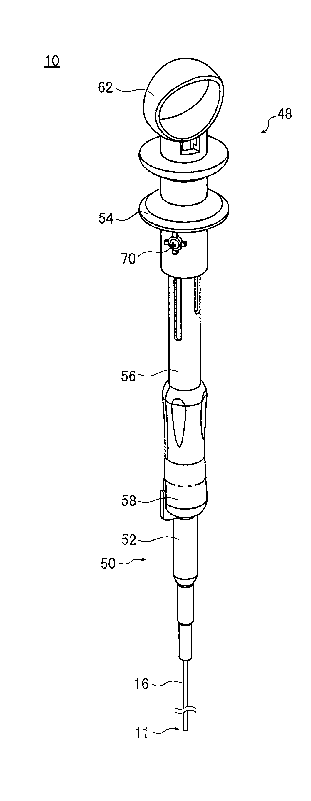
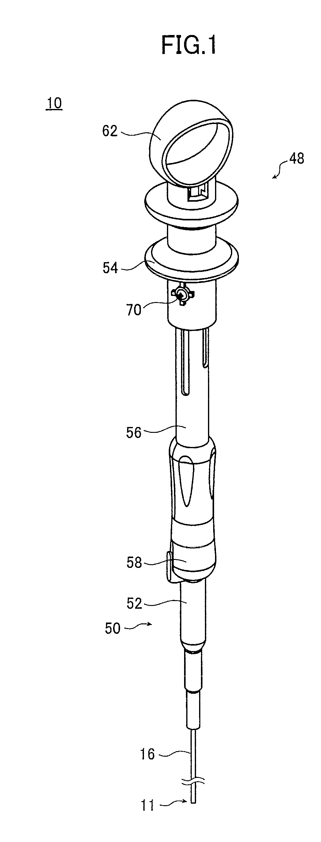
[0066]FIG. 1 illustrates a schematic configuration of a successive clipping device (hereinafter also referred to simply as “clipping device”) 10 using a manipulating handle according to Embodiment 1 of the present invention. The clipping device 10 includes a manipulation operating portion 11 and a manipulating portion 50.

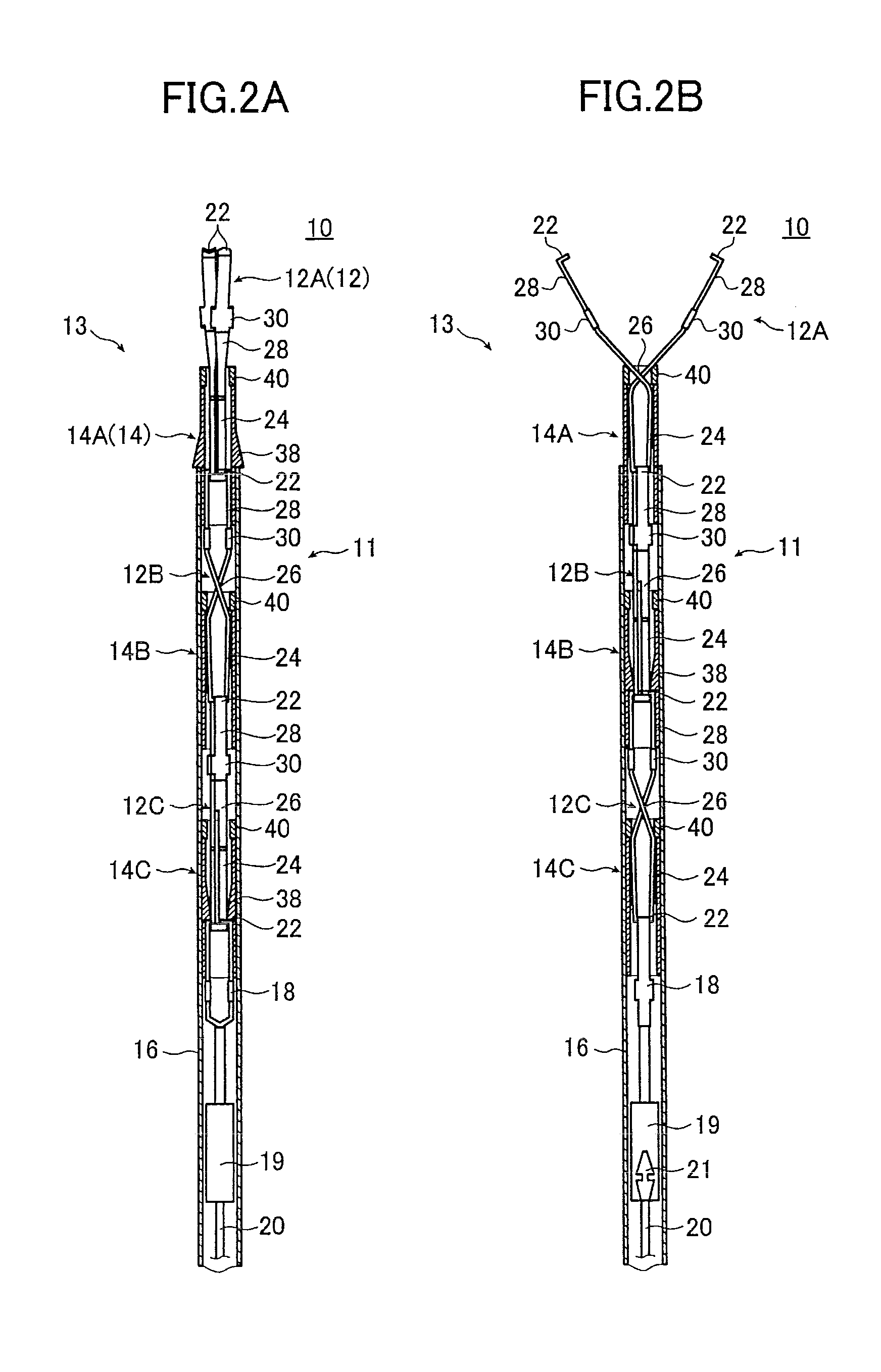
[0067]FIG. 2A is a cross-sectional view illustrating a schematic configuration of the manipulation operating portion 11 of the successive clipping device 10. FIG. 2B is a cross-sectional view of the manipulation operating portion 11 when viewed at an angle 90-degree different from the viewing angle of FIG. 2A.

[0068]In the following description, a lower end portion (on the side with the manipulation operating portion 11) in FIG. 1, and an upper end portion in each of FIGS. 2A and 2B are each called a “forward end”, and a lower end portion in each of FIGS. 2A and 2B, and an upper end portion (on the side with the manipulating portion 50) of FIG. 1 are each called a “p...

embodiment 2

[0200]In the manipulating handle of Embodiment 1, the distance from the maximum protruding position to the standard protruding position of each of the slider guide grooves is used as the buffer for variations in the dimensions of the components and for the difference between the inner and outer circumferences of the wire and the sheath, and the skirt portions of the clip are shaped to open irrespective of an error. However, the region of the slider guide groove extending from the maximum protruding position to the standard protruding position may be curved in the rotating direction of the slider.

[0201]FIG. 11 is a partial developed view of the outer circumferential surface of a slider guide used in a manipulating handle according to Embodiment 2.

[0202]A slider guide 80 having slider guide grooves 82A, 82B, 82C, and 82D illustrated in FIG. 11 has the same configuration as that of the slider guide 56 having the slider guide grooves 66A, 66B, 66C, and 66D illustrated in FIGS. 7A, 7B, a...

embodiment 3

[0210]In Embodiments 1 and 2, the slider guides provided with the slider guide grooves are used. However, it is also possible to form a slider guide with steps corresponding to the respective protruding positions of the individual clips instead of the slider guide grooves.

[0211]FIG. 12 is a partial developed view of the outer circumferential surface of a slider guide used in a manipulating handle according to Embodiment 3.

[0212]A slider guide 90 illustrated in FIG. 12 has the same configuration as that of the slider guide 56 in FIGS. 7A, 7B, and 10 except for using the steps instead of the slider guide grooves. Therefore, instead of the slider guide 56, the slider guide 90 can be used in the entirely same manner in the manipulating portion 50, the manipulating handle 48, and the clipping device 10 of the illustrated example.

[0213]As illustrated in the developed view of FIG. 12, a slider guide 90 is provided with five short sides 92 (sides 92A, 92B, 92C, 92D, and 92E) closer to the f...


PUM


Abstract

A manipulating handle for a successive clipping device comprises: a cylindrical handle main body connected to a sheath with a manipulating wire extending from the sheath being arranged in an interior thereof; a slider engaged with the manipulating wire for moving the manipulating wire in the axial direction of the handle main body; and a slider-movement-amount regulating member attached onto the outer circumferential surface of the handle main body so as to be rotatable in a circumferential direction of the handle main body, for regulating, according to a rotational position in a circumferential direction thereof, an amount of movement of the slider in the axial direction of the handle main body to one of a plurality of different amounts of movement required for respective clipping manipulations using a plurality of clips connected to the manipulating wire.

Description

BACKGROUND OF THE INVENTION[0001]The present invention relates to a technical field of an endoscopic clipping device used for stopping bleeding, suturing or closing a wound, or the like in a living body or the like. More particularly, the present invention relates to a manipulating handle for a successive clipping device which allows a plurality of clips to be used in succession, and a successive clipping device using such a manipulating handle as well as a manipulating handle for a clipping device using a single clip, and a clipping device using such a manipulating handle.[0002]Recently, an endoscopic clipping device is used for causing a clip to protrude from the forward end of an endocope inserted into a living body to pinch a bleeding portion or a portion to be treated after removal of a lesion tissue with the clip, thereby stopping the bleeding, suturing or closing the wound. In a conventionally used endoscopic clip, a single clip is detachably attached to the forward end of a ...

Claims


Application Information

Patent Timeline
Patent Type & Authority Patents(United States)
IPC IPC(8): A61B17/10
CPCA61B17/1285A61B17/2909A61B17/1222A61B17/1227A61B2017/0053A61B2017/2911A61B2017/2924
Inventor ITOH, KOJI
Owner FUJIFILM CORP
Why Eureka
Try Eureka