Light for room and building illumination

a technology for building illumination and room, applied in the direction of semiconductor devices for light sources, lighting and heating apparatuses, printed circuit non-printed electric components association, etc., can solve the problem of limited degree of freedom in housing design and arrangement of leds to provide particular light characteristics

Active Publication Date: 2019-06-25
BJB GMBH & CO KG
View PDF17 Cites 0 Cited by
  • Summary
  • Abstract
  • Description
  • Claims
  • Application Information

AI Technical Summary

Benefits of technology

[0010]Thus, it is an object of the invention to provide a light that is simple in configuration and is producible in an economical manner.
[0018]It is furthermore provided that the channel-shaped cavity is defined by face side terminal elements which are configured for example as a lamp socket or lamp holder which provides grid connection as well as attachment with minimal additional complexity.
[0023]The method can provide that the surface of the metal core circuit board is provided with support devices for a cover.

Problems solved by technology

Thus, however, degrees of freedom with respect to housing design and arrangement of LEDs to provide particular light characteristics are limited, however, there are numerous applications where these degrees of freedom are not necessary, for example when the light is used in particular for industrial or technical purposes.

Method used


Image

  • Light for room and building illumination
  • Light for room and building illumination
  • Light for room and building illumination

Examples


Embodiment Construction

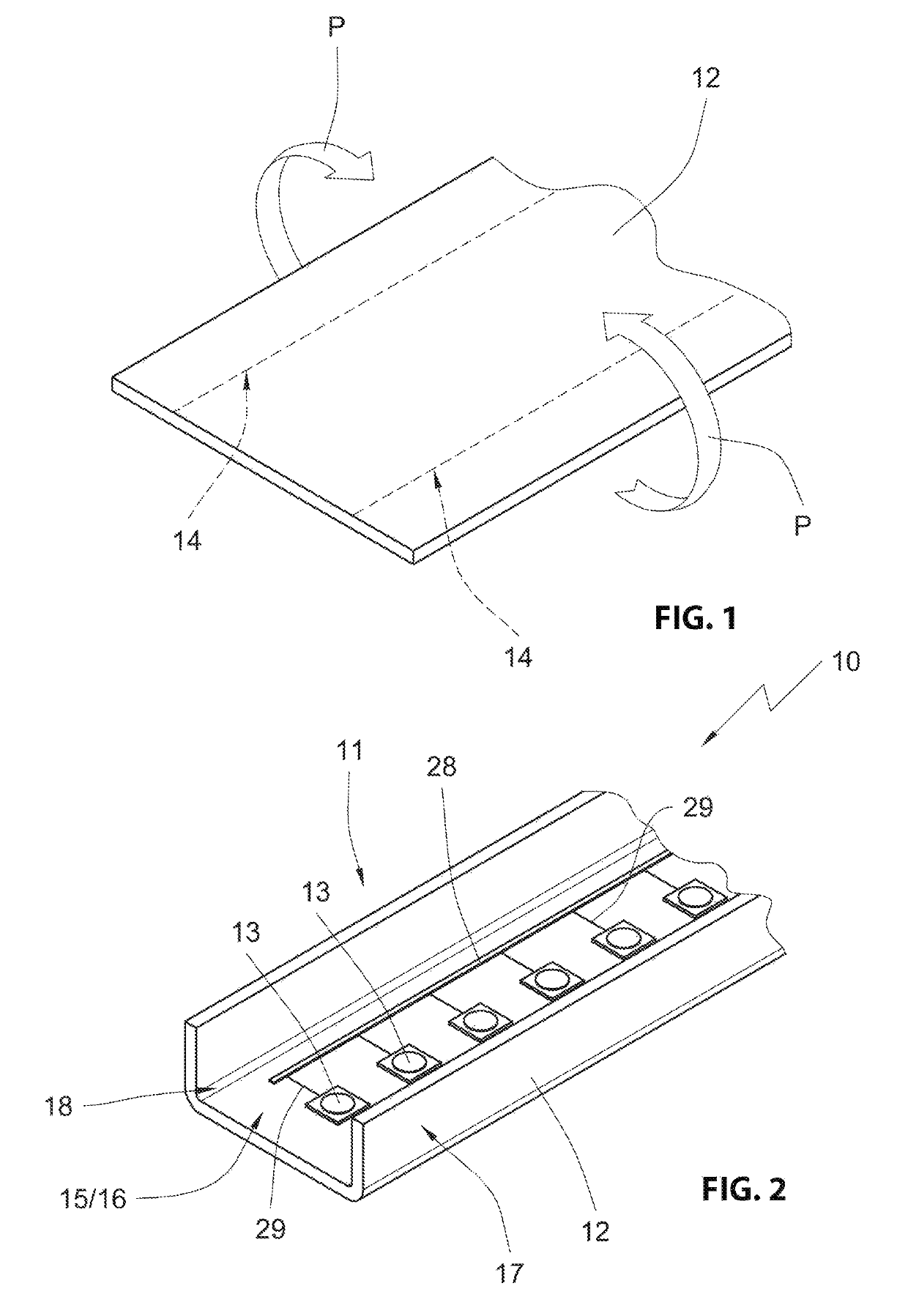
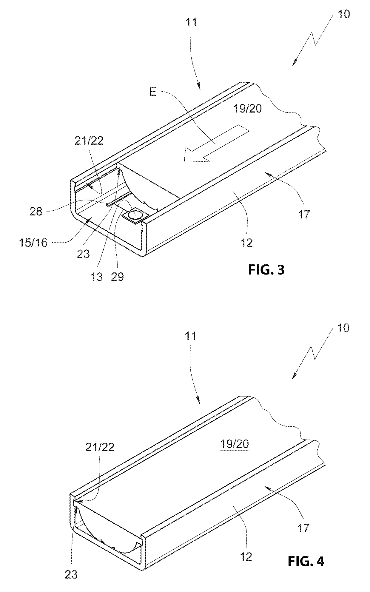
[0034]In the drawing figures the light according to the invention is overall designed reference numeral 10.

[0035]The light 10 includes a light housing 11 which is produced from a metal core circuit board 12 that is illustrated in FIG. 1. The illustration of the metal core circuit board 12 in FIG. 1 is highly simplified. Illustrating conductive paths and LEDs 13 that are arranged on the metal core circuit board 12 is omitted.

[0036]Advantageously the metal core circuit board is a flat element which is formed along two forming lines 14 to provide the light housing 11. In the embodiment the forming lines 14 are arranged parallel with one another and with a distance from each other. Forming according to the forming direction U illustrated by arrows 10 yields the light housing 11 of the light 10 that is illustrated in FIG. 2 in an exemplary manner and configured approximately channel-shaped.

[0037]The arrangement portion 15 formed for LEDs 13 and arranged between the forming lines 14 forms...


PUM


Abstract

A light for room and building illumination, the light comprising an illuminant, including a circuit board including a carrier material, an insulation layer applied to the carrier material at least on one side, conductive paths applied to the insulation layer, and at least one LED that is arranged on the insulation layer and functions as the illuminant, at least one light permeable cover arranged subsequent to the LED in a light exit direction, a light housing in which the circuit board is arranged, characterized in that the circuit board is a metal core circuit board which forms the light housing.

Description

RELATED APPLICATIONS[0001]This application claims priority from and incorporates by reference German patent application DE 10 2017 114 235.5 filed on Jun. 27, 2017.FIELD OF THE INVENTION[0002]The invention relates to a light for room and building illumination, the light comprising an illuminant, including[0003]a circuit board including a carrier material, an insulation layer applied to the carrier material at least on one side, conductive paths applied to the insulation layer, and at least one LED that is arranged on the insulation layer and functions as the illuminant,[0004]at least one light permeable cover arranged subsequent to the LED in a light exit direction,[0005]a light housing in which the circuit board is arranged.BACKGROUND OF THE INVENTION[0006]Lights of the generic type recited supra are known in the art. There are for example lights that use fluorescent tubes or classic gas discharge or incandescent bulbs which are retrofitable with LED illuminants.[0007]Modern lights...

Claims


Application Information

Patent Timeline
Patent Type & Authority Patents(United States)
IPC IPC(8): H01L33/60F21S4/28H05K1/02F21V29/507F21V15/01F21V3/02H05K1/05H05K1/18F21V5/04F21V29/503F21V17/04F21Y103/10F21Y115/10
CPCF21V15/01F21S4/28F21V3/02F21V29/503F21V29/507H05K1/0209H05K1/05H05K1/18F21V5/043F21Y2103/10F21Y2115/10H05K2201/10106F21V17/04
Inventor BAUMEISTER, OLAFPIEPER, MARKUS
Owner BJB GMBH & CO KG
Why Eureka
Try Eureka