Method and devices for calibrating a display unit comprising a display and autostereoscopic adapter disc

a display unit and adapter disc technology, applied in the field of methods and devices for the calibration (or “ electronic adjustment”) of a display unit, can solve the problems of insufficiently precise alignment between the optical and physical features of the display, corresponding cost disadvantages, and general inefficiency of the solution

Inactive Publication Date: 2012-07-03
RAUCHDOBLER EDUARD PAUL
View PDF10 Cites 5 Cited by
  • Summary
  • Abstract
  • Description
  • Claims
  • Application Information

AI Technical Summary

Benefits of technology

[0012]One advantage of solutions according to aspects of the present invention is that an optimal three-dimensional (3D) image playback can be achieved in a relativel

Problems solved by technology

However, one common problem in particular with multiview systems is that there is insufficiently exact alignment between the optical and physical features of the display and the optical and physical features of the attached adapter disc since the adapter disc, due to its detachable mounting on the display, cannot be po

Method used


Image

  • Method and devices for calibrating a display unit comprising a display and autostereoscopic adapter disc
  • Method and devices for calibrating a display unit comprising a display and autostereoscopic adapter disc
  • Method and devices for calibrating a display unit comprising a display and autostereoscopic adapter disc

Examples


Embodiment Construction

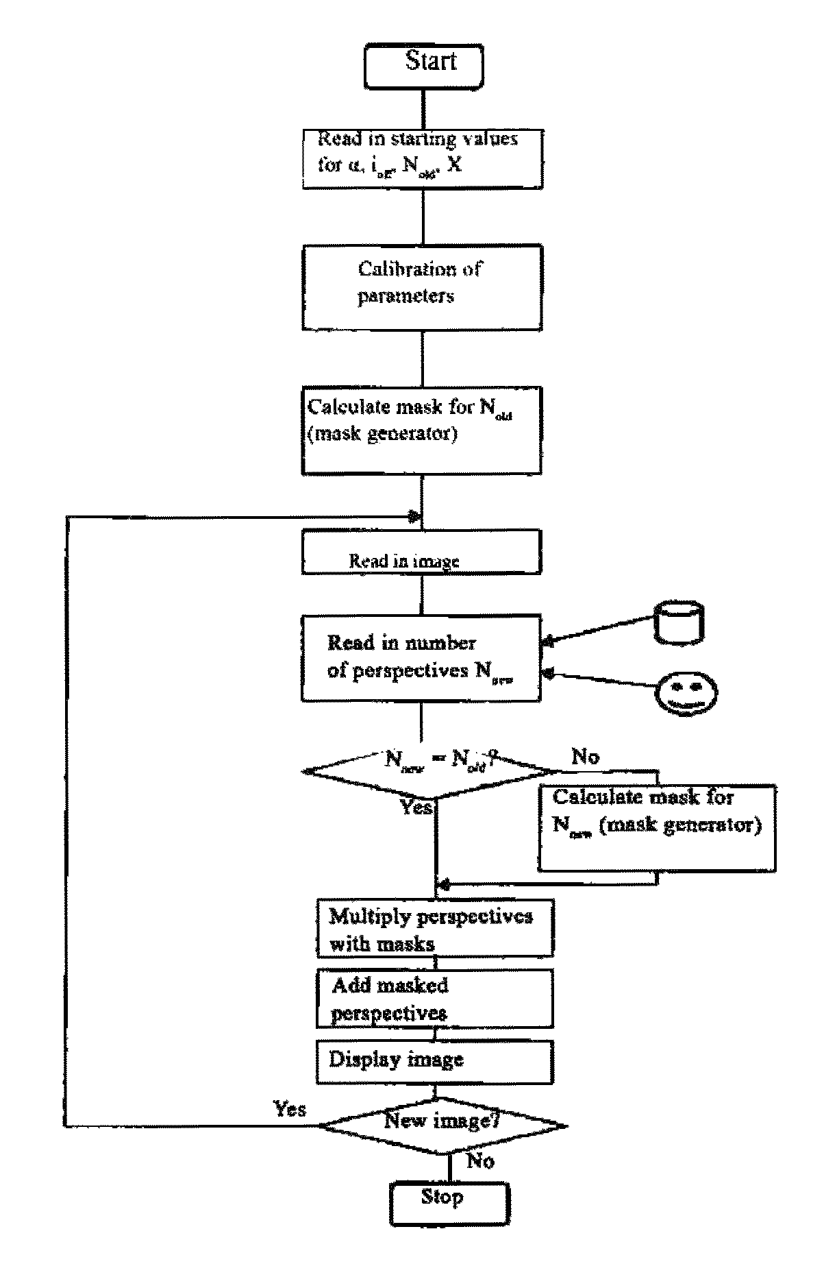
[0031]In an adapter disc that is permanently mounted, all optical and physical parameters are defined and substantially unchangeable so that the playback of images can be set relative to these parameters as well. These parameters are important in particular for defining which perspective n is to be displayed on which pixel or sub-pixel of the display.

[0032]In this context it must be mentioned that the pixel of an image (image element) in general is comprised of three sub-pixels, one each for the base colors red, green and blue (RGB). The method according to the invention can be executed on the pixel level as well as on the sub-pixel level. To this extent all explanations apply to both alternatives.

[0033]Based on the laws of optics and, for example, U.S. Pat. No. 4,668,063, a selected perspective n is based on the following formula:

n=(i+ioff−3j tan α)mod X*Ntot / X.  (1)

[0034]In this formula: n=selected perspective,[0035]i=horizontal index of a pixel or sub-pixel, i=1, . . . , I[0036]i...


PUM


Abstract

A method and a device for calibration (or “electronic” adjustment) of a display unit are provided and include a display and autostereoscopic adapter disc, particularly provided for fixing to the display. A method and a device for generation or playback of 3D images by the display unit including autostereoscopic adapter disc and display are also provided. Misalignment of the adapted disc with the display are compensated for by corresponding adjustment of the image display on the display.

Description

BACKGROUND AND SUMMARY[0001]The invention concerns a method and device for the calibration (or “electronic adjustment”) of a display unit, comprising a display and autostereoscopic adapter disc, particularly provided for detachable mounting to the display. The invention furthermore concerns a method and a device for the generation or playback of 3D images by means of said display unit comprising an autostereoscopic adapter disc and display. The invention finally concerns an autostereoscopic adapter disc that is especially suitable for the use with these methods and devices.[0002]Adapter discs of this type are known, for example, in the form of lenticular screen discs, lenticular discs, liquid lense discs or nano-lense discs that generally are comprised of layers of multiple individual discs and are placed on the screen surface of a display. Such a display unit comprised of an adapter disc and a display can be used to provide each eye of a viewer with a different perspective without ...

Claims


Application Information

Patent Timeline
IPC IPC(8): G06T15/00G02B30/27G02B30/30
CPCG02B7/00H04N13/111H04N13/302H04N13/305H04N13/327H04N13/351H04N13/359H04N13/361G02B30/27G02B30/30
Inventor NASKE, ROLF-DIETERCOCHIUS, GABRIELANASKE, IVO-HENNING
Owner RAUCHDOBLER EDUARD PAUL
Why Eureka
Try Eureka