Shear punching die assemblies

a technology of die assembly and die, which is applied in the direction of ejection devices, metal working devices, manufacturing tools, etc., can solve the problems of further speeding up of achieve the effect of effectively preventing work, simple speeding up the punching operation of the material, and easy speeding up the manufacturing speed of the work

Active Publication Date: 2012-07-10
TOYOTA BOSHOKU KK
View PDF16 Cites 3 Cited by
  • Summary
  • Abstract
  • Description
  • Claims
  • Application Information

AI Technical Summary

Benefits of technology

[0007]According to the present embodiment, the work can be rapidly ejected from the second die unit because a hydraulic removing mechanism is not used. In addition, the work can be automatically removed from the second die unit when the first and second die units are opened. Therefore, a manufacturing speed of the work can be easily speeded up by simply speeding up a punching operation of the material.
[0008]In addition, the work is reliably retained on the second die unit until the first and second die units are sufficiently opened. Therefore, the work can be effectively prevented from interfering with a processed material when the first and second die units are opened. In particular, the work can be effectively prevented from reengaging a punched hole of the processed material. Therefore, an extra time is not required for removing the work from the processed material. This may contribute to further speeding up of the manufacturing speed of the work.
[0013]In a still further embodiment of the invention, the arm may have a guide slot that is arranged and constructed such that the rod can move therealong when the upper and lower die units are relatively moved. The protrusion may be projected into the guide slot such that a width of the guide slot can be reduced.

Problems solved by technology

This may contribute to further speeding up of the manufacturing speed of the work.

Method used


Image

  • Shear punching die assemblies
  • Shear punching die assemblies
  • Shear punching die assemblies

Examples


Embodiment Construction

[0027]Detailed representative embodiments of the present invention will now be described with reference to the drawings.

First Detailed Representative Embodiment

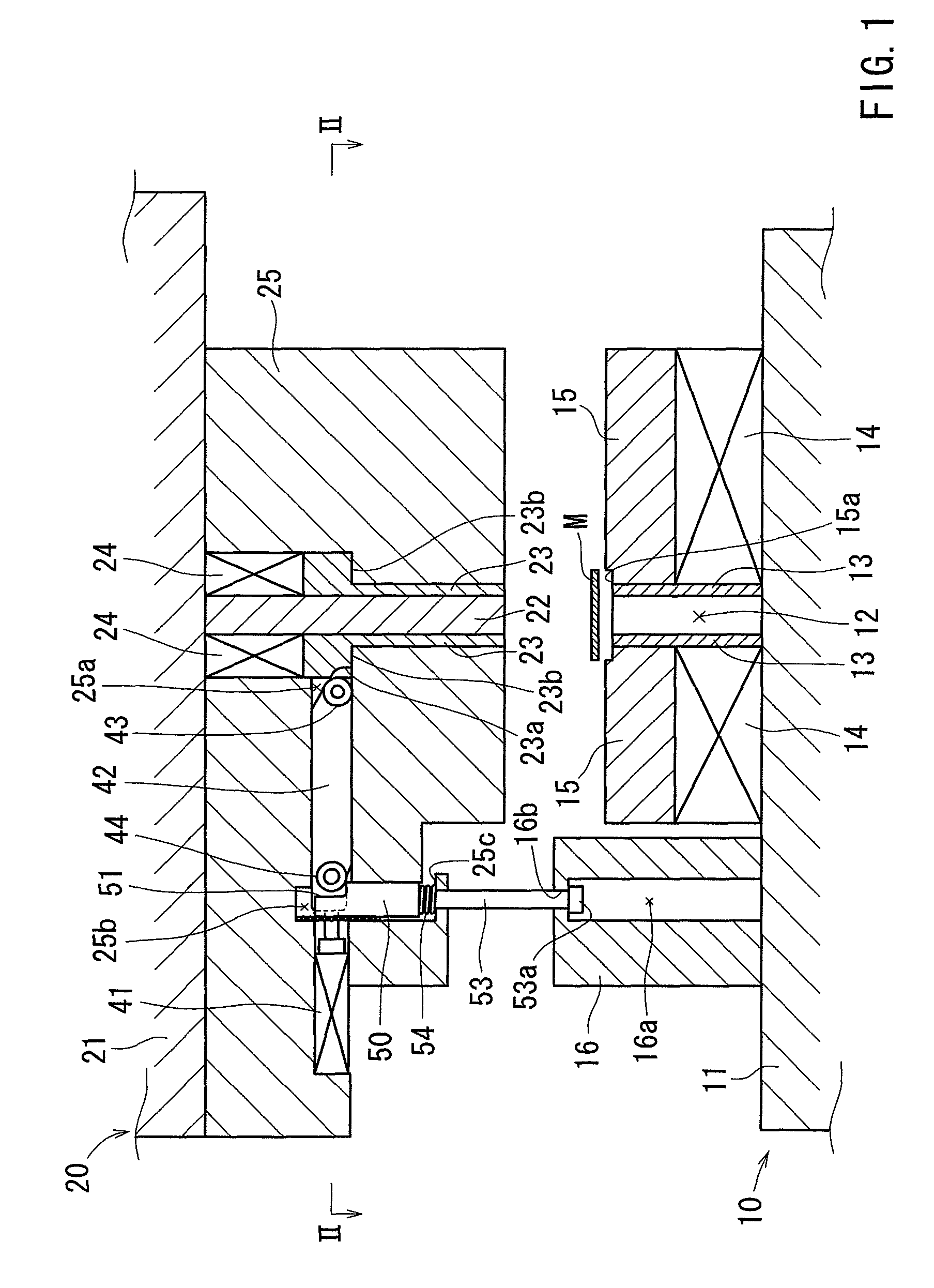
[0028]First, a first embodiment of the present invention will be described with reference to FIGS. 1 to 7.

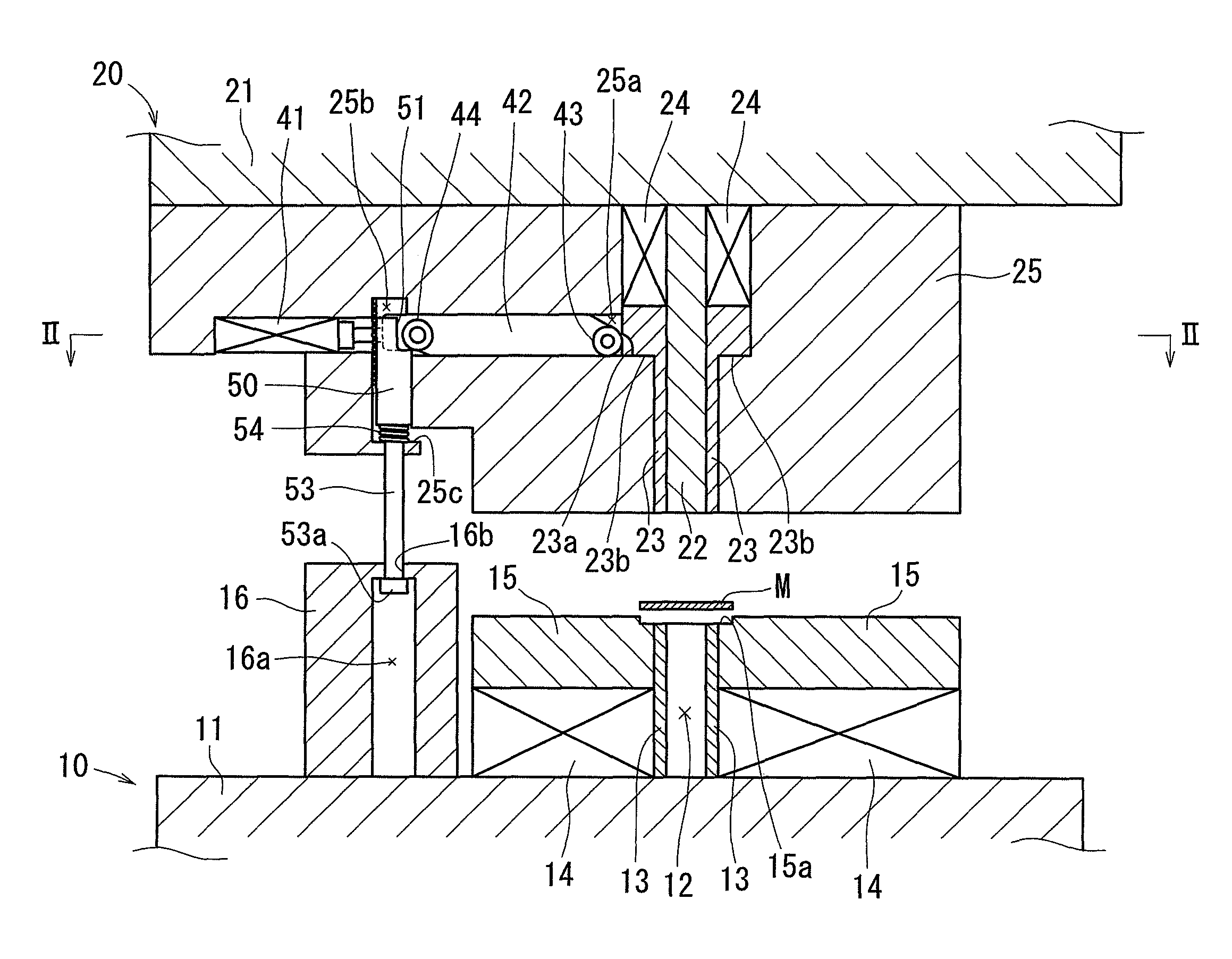
[0029]A shear punching die assembly is intended to press or punch a strip-shaped metal sheet material M in order to form a molded material or work W. The work W may be utilized as, for example, a construction element of a seat reclining device of a vehicle. Further, the shear punching die assembly is constructed such that the sheet material M is continuously fed vertically to a plane in FIGS. 1 and 3-7.

[0030]As shown in, for example, FIGS. 1 and 2, the shear punching die assembly may include a lower or first die unit (a stationary die unit) 10 that is associated with a lower or first base 11 and an upper or second die unit (a movable die unit) 20 that is associated with an upper or second base 21. Further, the second base...


PUM

PropertyMeasurementUnit
distanceaaaaaaaaaa
forceaaaaaaaaaa
biasing forceaaaaaaaaaa

Abstract

A shear punching die assembly having first and second die units in which a material is punched to form a work while the material is clamped between the first and second die units is taught that preferably include a main punch contained in the first die unit and having a cross-sectional shape corresponding to a shape of the work, an ejector contained in the second die unit and positioned axially opposite to the main punch, an ejector biasing member normally biasing the ejector toward the main punch, an ejector retaining device that is capable of acting on the ejector when the first and second die units are in a closed condition, thereby retaining the ejector in a predetermined position, and an ejector releasing device that is capable of acting on the ejector retaining device when the first and second die units are opened over a desired distance, thereby releasing the ejector.

Description

TECHNICAL FIELD[0001]The present invention relates to shear punching die assemblies. More particularly, the present invention relates to shear punching die assemblies in which a material is pressed or punched to form a work while the material is clamped between upper and lower die units of the shear punching die assembly.BACKGROUND ART[0002]A known shear punching die assembly includes a lower die unit that has a main punch and a stripper disposed around the main punch, and an upper die unit that has an ejector positioned axially opposite to the main punch and a die disposed around the ejector. In the known art, a material (a sheet material) is transferred and placed between upper and lower die units of the shear punching die assembly. Thereafter, the upper and lower die units are closed (i.e., a die closing operation is performed), so that the main punch of the lower die unit engages the die of the upper die unit. As a result, the material is punched out by the main punch, so that a...

Claims


Application Information

Patent Timeline
Patent Type & Authority Patents(United States)
IPC IPC(8): B21D45/06B26D7/06
CPCB21D45/04B21D28/16B21D45/003B21D45/10Y10T83/2133
Inventor FUJIMURA, SHIROUUSHIDA, KOUHEIWATANABE, TAKUMA
Owner TOYOTA BOSHOKU KK
Why Eureka
Try Eureka