Spooling device of wire rod

A winding device and wire technology, applied in electromechanical devices, manufacturing motor generators, electrical components, etc., can solve the problems of rising unit price of devices, expensive servo motors, and large-scale devices, so as to reduce gaps and avoid random winding. , the effect of easy high-speed

Active Publication Date: 2011-11-09
NITTOKU ENG CO LTD
View PDF4 Cites 3 Cited by
  • Summary
  • Abstract
  • Description
  • Claims
  • Application Information

AI Technical Summary

Problems solved by technology

Since such a servo motor is very expensive and large in size, when high-speed winding is pursued, there will be a problem that the unit price of the device will increase and the size of the device will increase.

Method used


Image

  • Spooling device of wire rod
  • Spooling device of wire rod
  • Spooling device of wire rod

Examples


Embodiment Construction

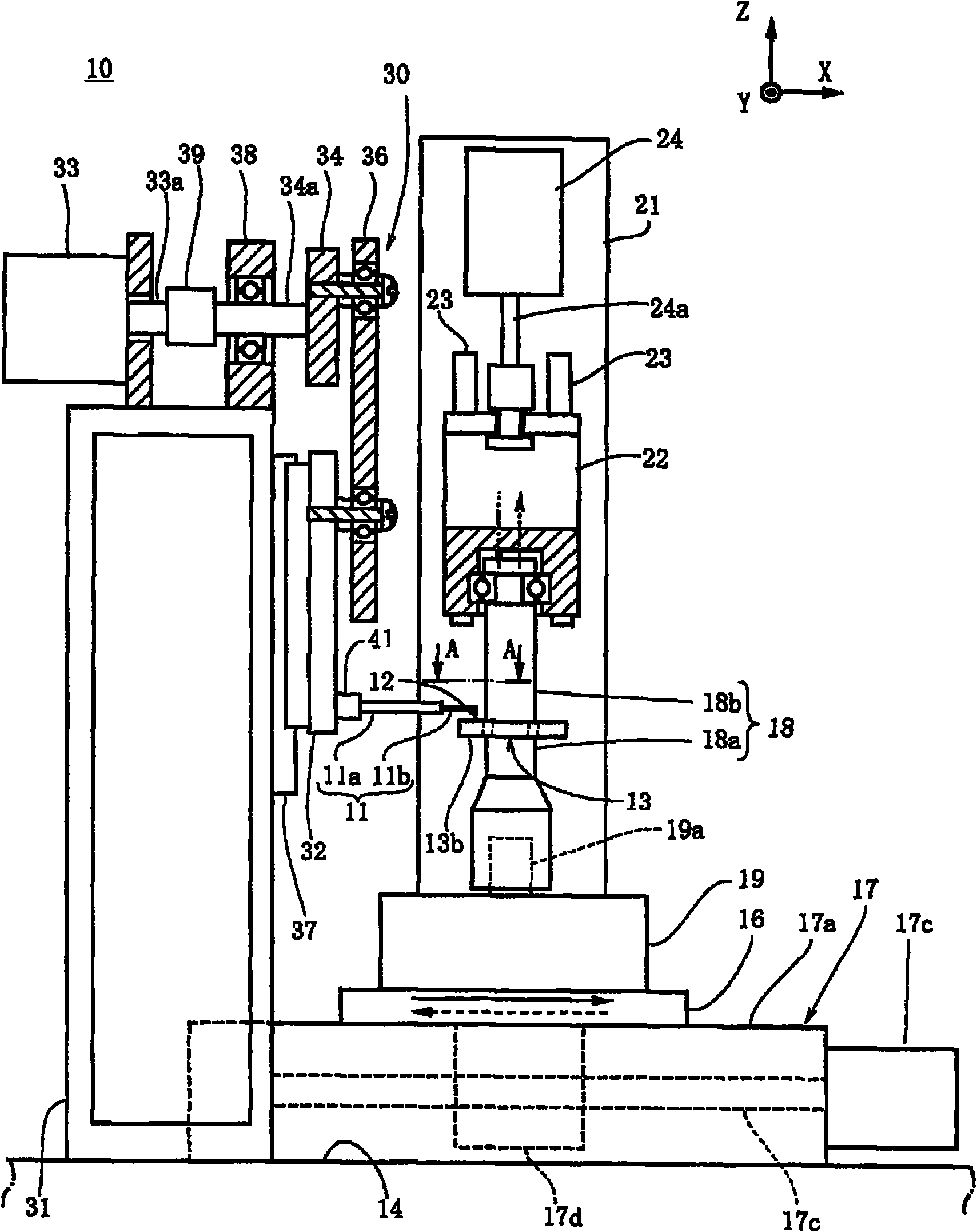
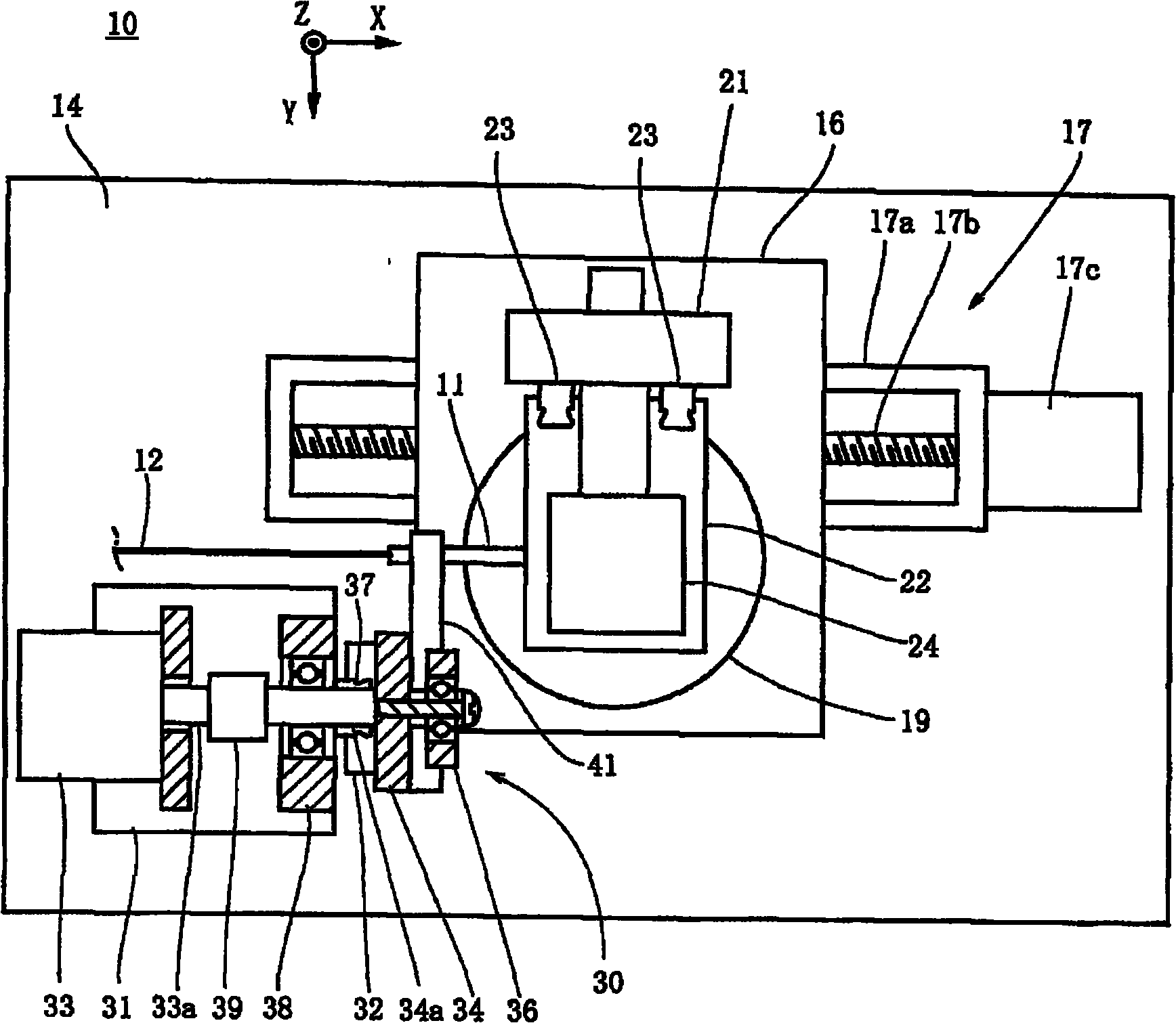
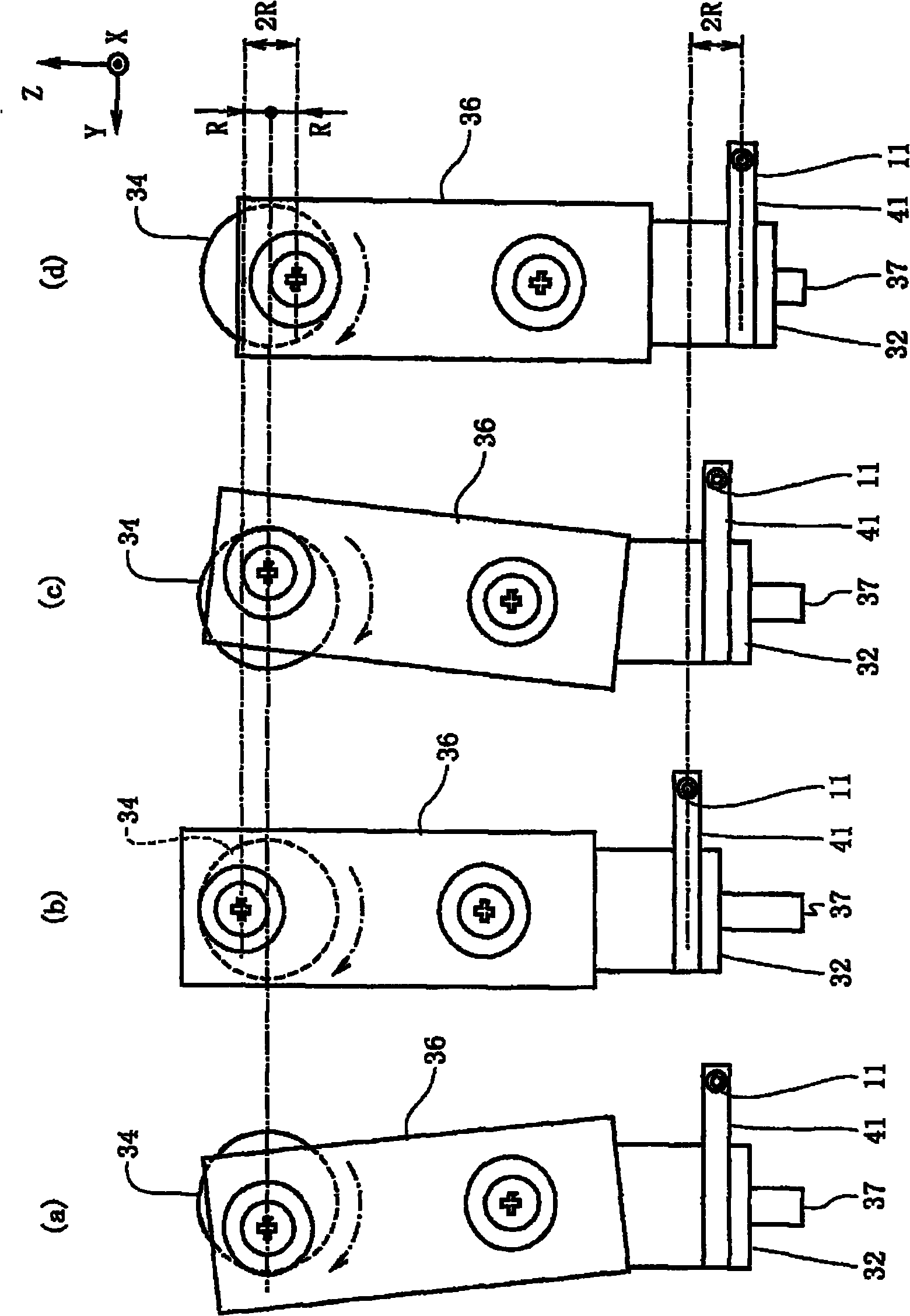
[0030] Hereinafter, the best mode for carrying out the present invention will be described based on the drawings.

[0031] exist figure 1 and figure 2 The wire winding device 10 of the present invention is shown in . In each figure, three axes X, Y, and Z that are perpendicular to each other are set, and the X axis is defined as an axis extending in a substantially horizontal front-rear direction, the Y axis is defined as an axis extending in a substantially horizontal horizontal direction, and the Z axis is defined as an axis extending approximately horizontally. The structure of the winding device 10 will be described as an axis extending in the vertical direction. This winding device 10 is a device that winds the wire 12 drawn out from the nozzle 11 around the magnetic pole 13 b of the stator core 13 . and if Figure 7 As shown, the stator core 13 of this embodiment uses an external gear-type stator core, and includes: an annular ring portion 13a and a plurality of mag...


PUM


Abstract

The invention provides a spooling device of a wire rod, which can wind the wire rod on the magnetic poles of a stator with high accuracy and high speed. The spooling device winds the wire rod led out from a wire mouth on the magnetic poles of the stator. The spooling device includes a wire mouth moving mechanism enabling the wire mouth to move along a direction vertical to the shaft of the magnetic pole. The wire mouth moving mechanism comprises a pedestal, a movable stage which can be disposed on the pedestal in a manner of moving along a direction vertical to the axle center of the magneticpole and is provided with the wire mouth, a drive source which is disposed on the pedestal and enables a rotating component to rotate, and a connection component with one end being supported through pivot bearing to the rotation center deviating from the rotation component and the other end being supported through pivot bearing to the movable stage. A stator core motion mechanism which enables a stator core to move for the shaking of the magnetic pole is provided. The wire mouth mechanism enables the wire mouth to move along directions which are approximately vertical to the shaft of the magnetic pole and different from the shaking direction of the magnetic pole.

Description

technical field [0001] The present invention relates to a wire winding device, which winds the wire led out from the tip of a wire nozzle on a magnetic pole protruding in the radial direction of a stator. Background technique [0002] In the past, the stator of the internal gear motor was formed by winding a wire around a plurality of magnetic poles protruding toward the inner peripheral side of the stator core. The stator core was formed by laminating a plurality of ring-shaped members. It is formed by winding wires around a plurality of magnetic poles protruding radially from the outer peripheral side of the stator core. Conventionally, winding to each magnetic pole of the stator core has been performed by causing a nozzle attached to the main shaft to revolve around each magnetic pole, for example, in a circular locus as the main shaft rotates. Such spindle-type winding can speed up the winding operation. [0003] However, in such spindle-type winding, it is necessary t...

Claims


Application Information

Patent Timeline
IPC IPC(8): H02K15/095
Inventor 田口广之
Owner NITTOKU ENG CO LTD
Why Eureka
Try Eureka