Needle plate and sewing machine provided therewith

a technology of needle plate and sewing machine, which is applied in the direction of sewing machine elements, sewing apparatus, textiles and paper, etc., can solve the problems of difficulty in detachment of second needle plate, troublesome two-stage operation, and the impact of needle or feed dog on the needle pla

Active Publication Date: 2012-07-10
BROTHER KOGYO KK
View PDF20 Cites 14 Cited by
  • Summary
  • Abstract
  • Description
  • Claims
  • Application Information

AI Technical Summary

Benefits of technology

[0008]Therefore, an object of the disclosure is to provide a needle plate in which the second needle plate can be attached to and detached from the first needle plate exceedingly easily and a sewing machine provided with the needle plate.
[0010]In the above-described construction, the second needle plate is caused to engage with the first needle plate when slid rearward from the front side of the first needle plate. The disengagement operating member is operated so as to be moved frontward from the rear side of the first needle plate, whereby the second needle plate is disengaged from the first needle plate. Accordingly, the second needle plate can easily be attached to the first needle plate by sliding the second needle plate. Moreover, in detaching the second needle plate, a detaching direction corresponds with an operating direction of the disengagement operating member. Accordingly, since the disengagement operating member is slid frontward together with the second needle plate, the second needle plate can be detached from the first needle plate only by a primary operation of the disengagement operating member. Consequently, the second needle plate can be attached to and detached from the first needle plate exceedingly easily.

Problems solved by technology

When the adjustment is not carried out accurately, there is a possibility that the needle or feed dog may collide with the needle plate.
Accordingly, the second needle plate is difficult to detach and a two-staged operation is troublesome.

Method used


Image

  • Needle plate and sewing machine provided therewith
  • Needle plate and sewing machine provided therewith
  • Needle plate and sewing machine provided therewith

Examples


Embodiment Construction

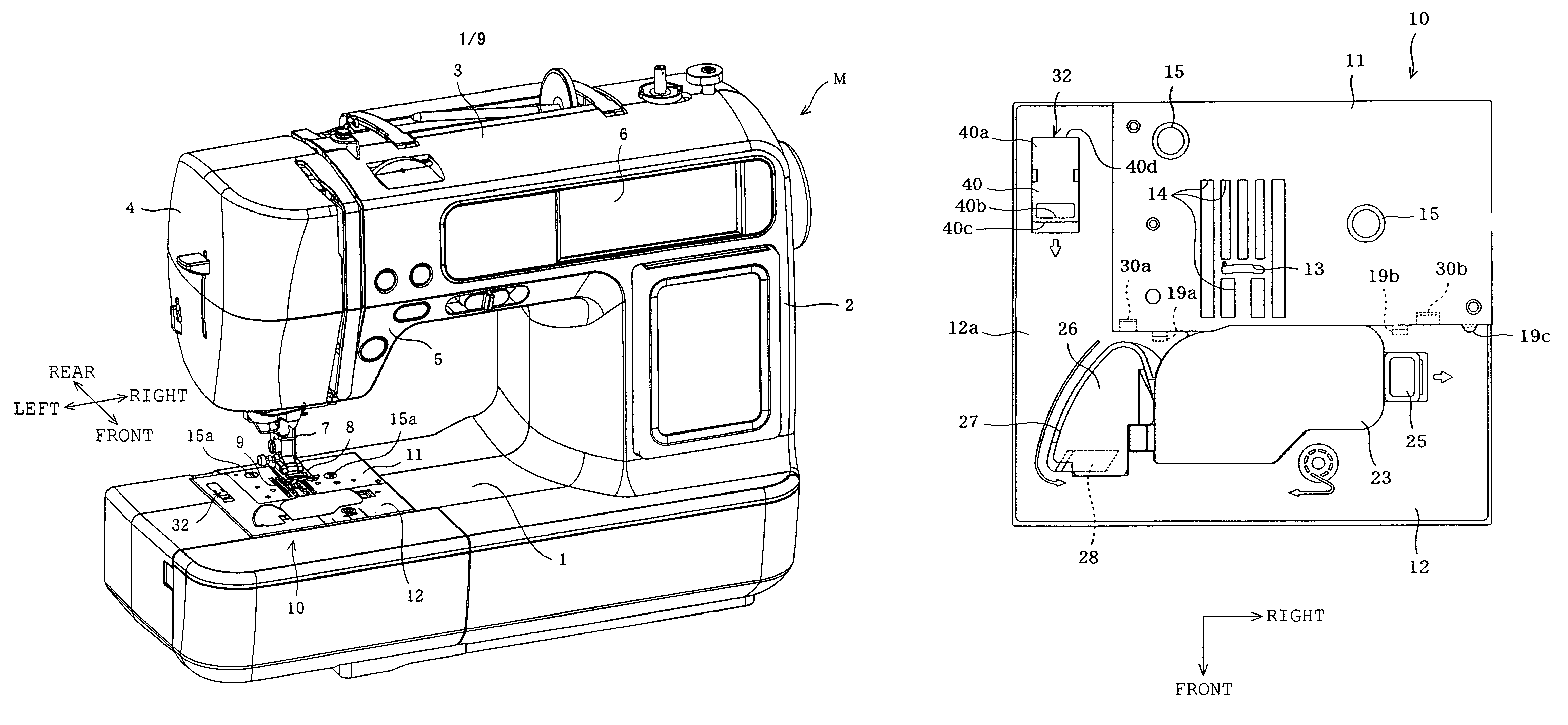
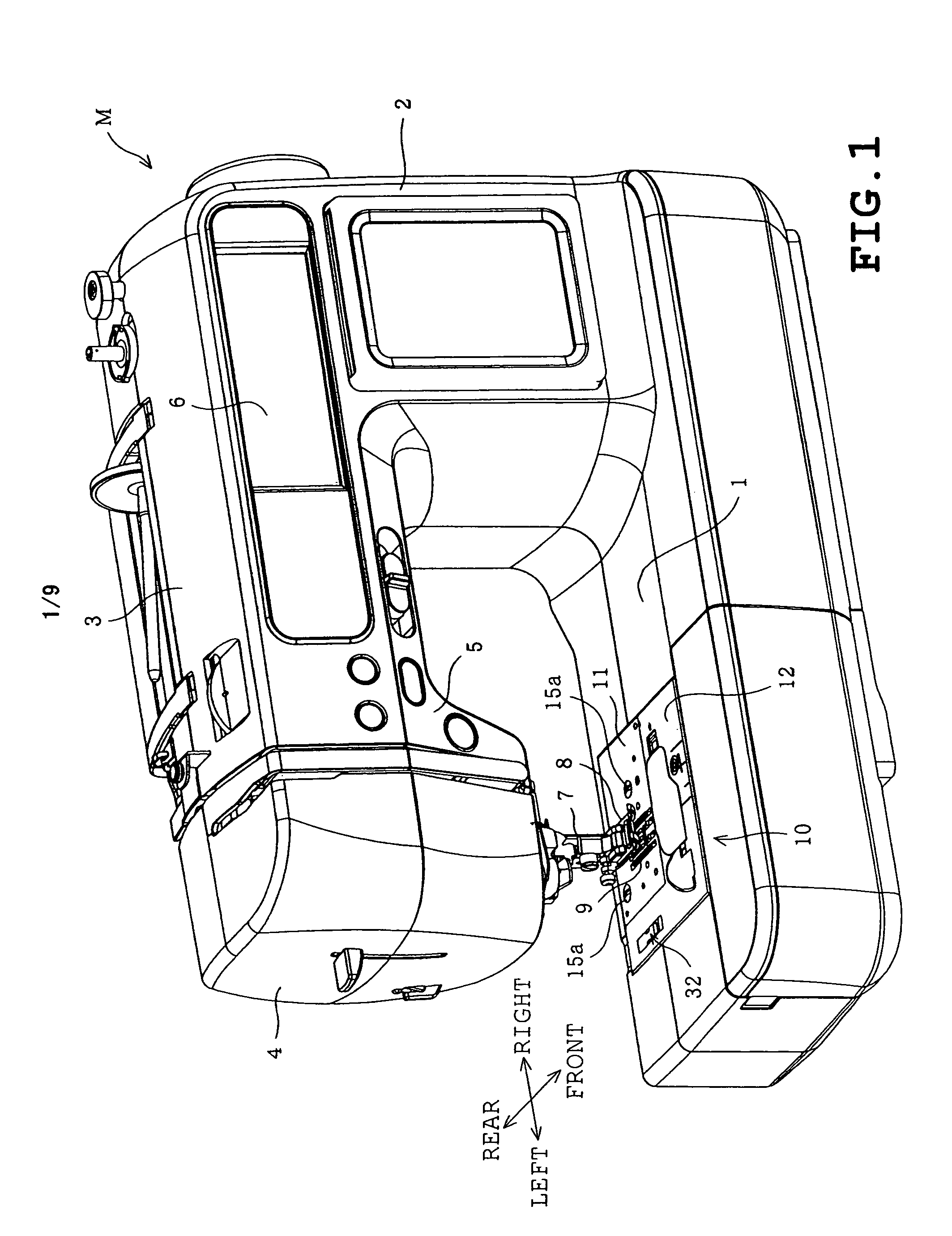
[0027]A first embodiment of the present disclosure will be described with reference to the accompanying drawings. Referring to FIG. 1, an entire sewing machine M is shown. In the following description, an operator is located in front of the sewing machine M. The sewing machine M includes a sewing bed 1, a sewing pillar 2 extending upward from a right end of the bed 1, a sewing arm 3 extending leftward from an upper end of the pillar 2 opposite the sewing machine bed 1 and a sewing head 4 mounted on a left end of the arm 3. The arm 3 has a front on which various operation switches 5 are provided, and a horizontal crystal liquid display 6 is provided on a front of the pillar 2.

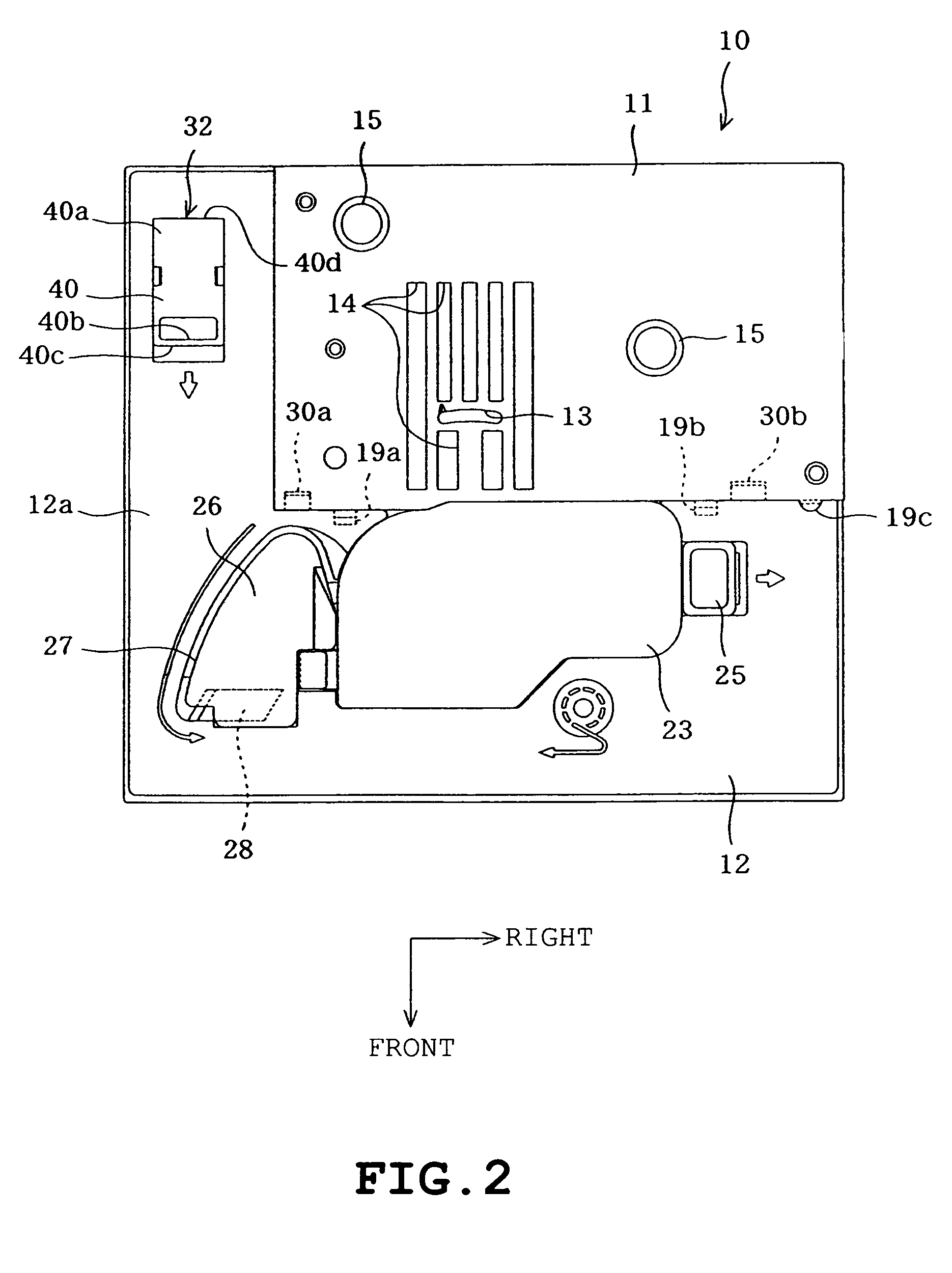
[0028]A sewing machine main shaft (not shown) is mounted inside the arm 3 so as to extend in a horizontal direction, and a sewing machine motor (not shown) is also provided inside the arm 3 for rotating the main shaft. A needle bar is provided in the head 4 although not shown in detail. The needle bar has a lowe...


PUM


Abstract

A needle plate for a sewing machine includes a first needle plate fixed to a sewing machine bed and formed with a needle hole through which a needle passes and a rectangular hole through which a feed dog appears, a second needle plate disposed in front of the first needle plate and detachably attached to the first needle plate, an engagement mechanism sliding the second needle plate rearward from a front side of the first needle plate, thereby engaging the second needle plate with the first needle plate, and a disengagement operating member located on the second needle plate so as to operate the engagement mechanism so that the second needle plate is disengaged from the first needle plate. The disengagement operating member is moved frontward from a rear side of the first needle plate thereby to disengage the second needle plate from the first needle plate.

Description

CROSS-REFERENCE TO RELATED APPLICATIONS[0001]This application is based upon and claims the benefit of priority from the prior Japanese Patent Application No. 2009-3468 filed on Jan. 9, 2009, the entire contents of which are incorporated herein by reference.BACKGROUND[0002]1. Technical Field[0003]The present disclosure relates to a needle plate having a first needle plate fixed to a sewing machine bed and a second needle plate detachably attached to the first needle plate, and a sewing machine provided with the needle plate.[0004]2. Description of the Related Art[0005]Conventional sewing machine have been provided with a needle plate screwed to an upper surface of the sewing machine bed (a bed portion) and having a needle hole through which a needle is penetrable and a rectangular hole through which a feed dog feeding a workpiece cloth is retractable. The sewing machine has also been provided with the horizontal hook mechanism disposed in the bed. In this type of sewing machine, when...

Claims


Application Information

Patent Timeline
Patent Type & Authority Patents(United States)
IPC IPC(8): D05B73/12D05B73/00
CPCD05B73/12
Inventor FUKAO, HIROAKI
Owner BROTHER KOGYO KK
Why Eureka
Try Eureka