
Robust rotational position alignment using a relative position encoder

a relative position encoder and rotational position technology, applied in the direction of dynamo-electric motors/converters, starters, magnetic circuits, etc., can solve the problems of inability to achieve the desired angular displacement within a specified time period, markers may not be where they are expected, and the initialization routine cannot be tied, etc., to achieve accurate and robust detection of an angular position

Active Publication Date: 2012-07-10
PARKER INTANGIBLES LLC
View PDF12 Cites 7 Cited by
  • Summary
  • Abstract
  • Description
  • Claims
  • Application Information

AI Technical Summary

Benefits of technology

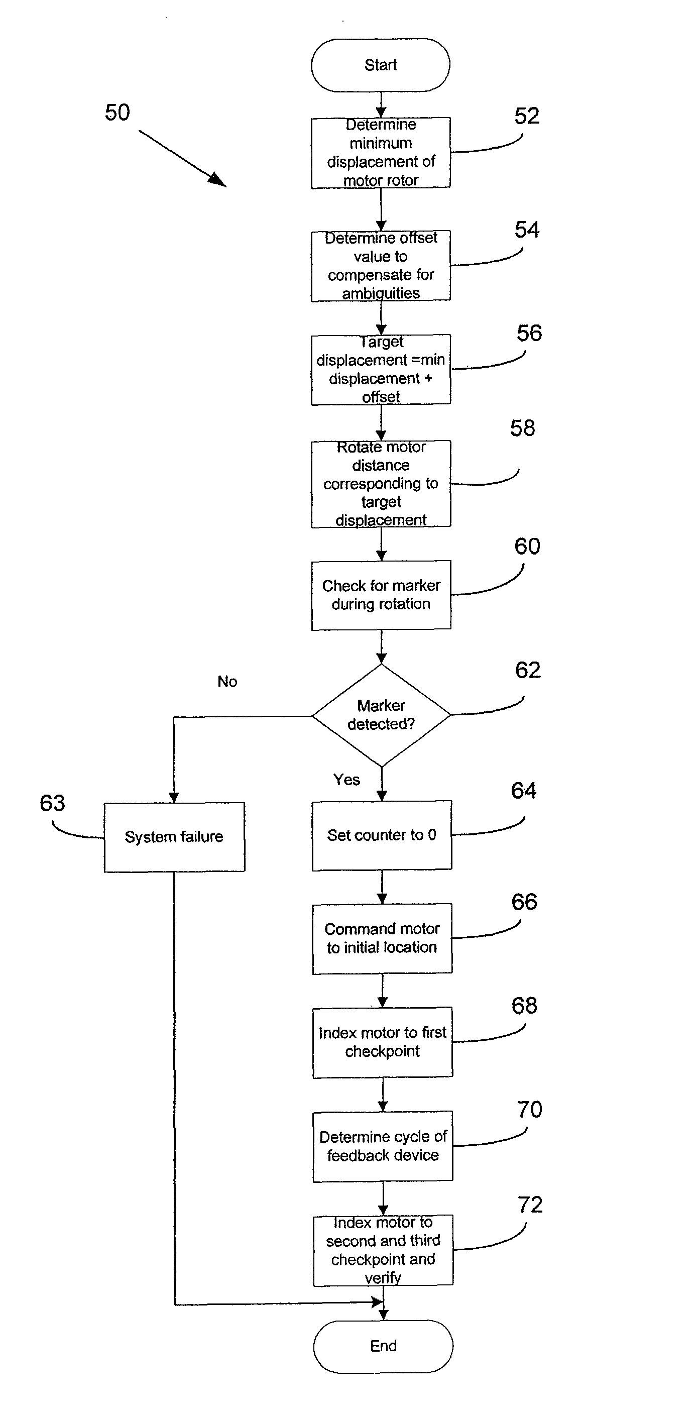
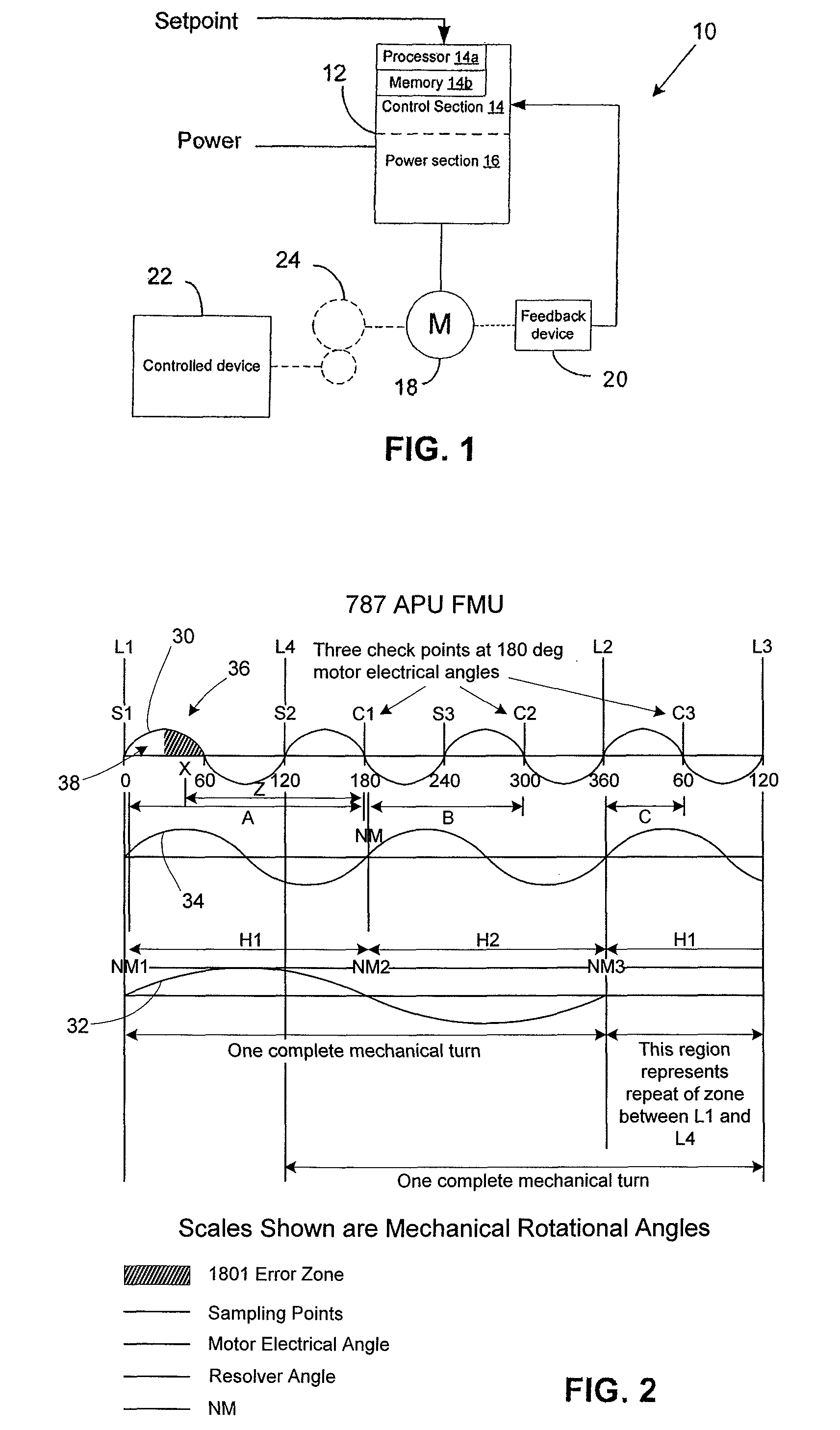
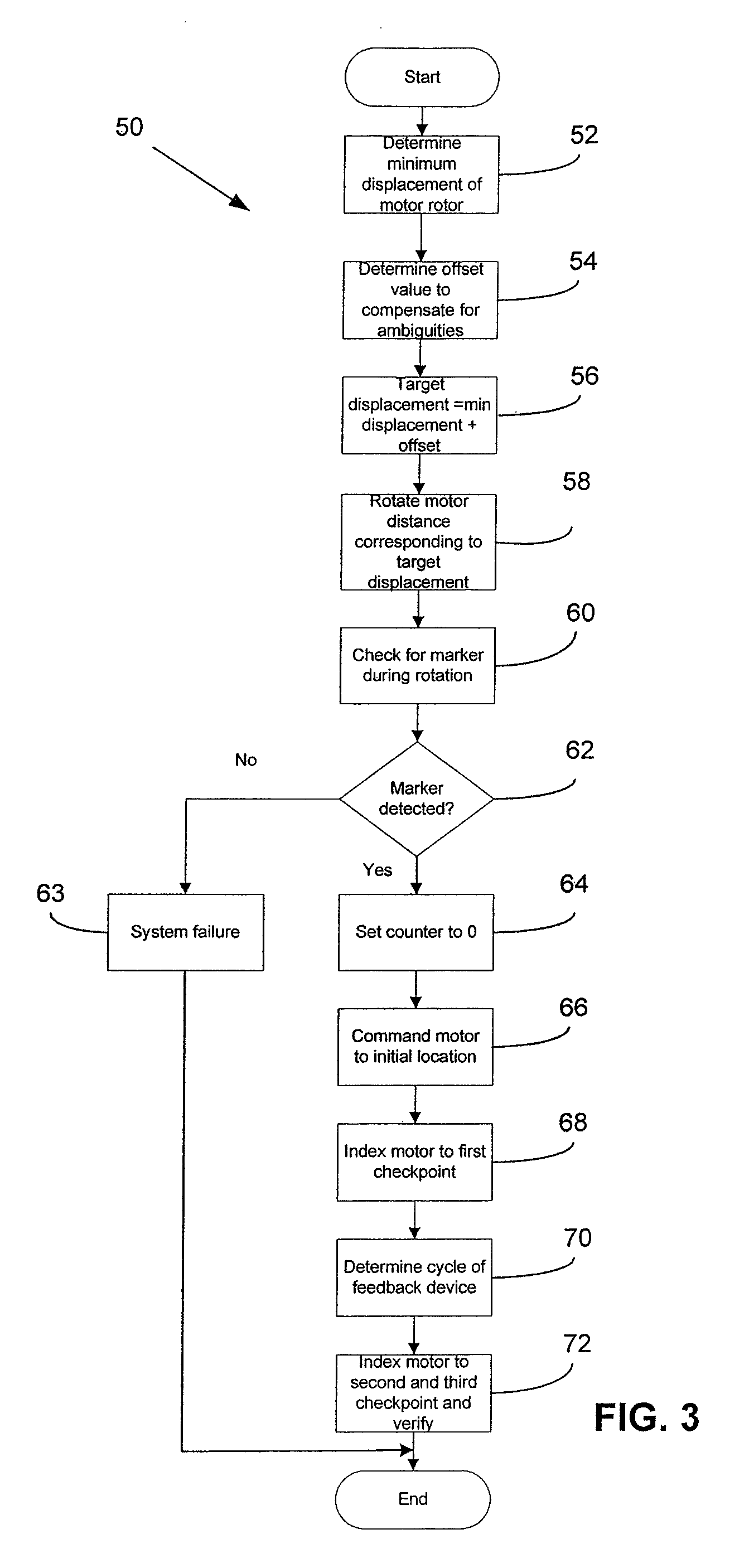
[0008]A method and apparatus in accordance with the present invention enable accurate and robust detection of an angular position of a feedback device, such as an encoder or resolver, relative to a rotating member coupled to the position feedback device without additional hardware. More particularly, a rotating member, such as a motor rotor, coupled to the position feedback device is commanded to execute an angular move such that the total angular displacement of the motor rotor ensures that more than one electrical cycle of the feedback device is completed (e.g., the electrical angular rotation of the position feedback device is greater than an apparent angular displacement between two consecutive markers of the position feedback device). This enables at least one marker of the feedback device to be detected during initialization.

Problems solved by technology

It has been discovered that failure of the initialization routine can be tied to improper rotation of the rotating member (and thus of the position feedback device).
For example, if the rotating member (e.g., an AC motor rotor) is commanded to rotate a specified angular displacement but, due to finite dynamic response or load on the rotating member (e.g., viscous fuel at low temperature) the rotating member rotates more slowly than expected, it may not achieve the desired angular displacement within a specified time period.
Another issue that may affect the initialization routine is manufacturing tolerances within the feedback device itself as well as the alignment of the marker with respect to electrical angle for commutation (during manufacture alignment of the marker may be arbitrary—such arbitrary alignment could be addressed via a calibration step.
Due to manufacturing tolerances, however, these markers may not be where they are expected to be.
These issues can lead to improper alignment between the rotating member and an angular position of the feedback device.

Method used


Image

  • Robust rotational position alignment using a relative position encoder
  • Robust rotational position alignment using a relative position encoder
  • Robust rotational position alignment using a relative position encoder

Examples


Embodiment Construction

[0032]The principles of the invention will now be described with reference to the drawings, wherein like reference numbers refer to like components throughout.

[0033]A method and device in accordance with the present invention enable a relative position feedback device to accurately and robustly provide absolute position feedback. As used herein, a relative position feedback device is a device that provides relative angular information with respect to a reference point, e.g. North Mark, and the angular information is a multiple of the mechanical angle of the feedback device's shaft. Such relative position feedback device, when coupled to a motor that does not have a unique mapping with the relative position feedback device (e.g., a 1:1 mapping such that the number of motor electrical cycles per revolution are equal to the number of feedback device electrical cycles per revolution) cannot directly provide angular position of the motor rotor within one mechanical revolution. An absolut...


PUM


Abstract

A robust method for detecting a relative position of a feedback device, such as an encoder or resolver, coupled to a shaft, such as a motor shaft, is provided. To detect the relative position, electrical commands are issued in an open loop mode to spin the motor shaft an amount greater than the apparent rotational angle between two consecutive markers of the position feedback device, such that the net mechanical rotation is equal to or greater than the total rotational angle between two consecutive markers.

Description

RELATED APPLICATION DATA[0001]This application claims priority of U.S. Provisional Application No. 61 / 229,310 filed on Jul. 29, 2009, which is incorporated herein by reference in its entirety.FIELD OF THE INVENTION[0002]The present invention relates generally to motor control and, more particularly, to aligning a relative angular position of a position feedback device, such as an encoder or a resolver, with a motor shaft.BACKGROUND[0003]Position feedback devices, such as encoders and resolvers, for example, are used to monitor the motion of devices, such as a motor shaft, for example. Generally, the position of the shaft is monitored in terms of angular position and / or number of revolutions. Encoders typically use a code wheel attached to the shaft to modulate light as the shaft and the code wheel rotate, while resolvers use rotating windings (e.g., a rotating transformer) to determine an angular position of the shaft.[0004]In motor control systems, an initialization routine is typi...

Claims


Application Information

Patent Timeline
Patent Type & Authority Patents(United States)
IPC IPC(8): H02P6/04
CPCH02P1/46H02P6/20H02P25/023H02P25/03
Inventor LIN, YUN-CHICH "JACK"
Owner PARKER INTANGIBLES LLC
Learn More