State estimation apparatus, state estimation method, integrated circuit, and non-transitory computer-readable storage medium

a technology of state estimation and state estimation, applied in the field of state estimation apparatus, state estimation method, integrated circuit, and non-transitory computer-readable storage medium, can solve the problems of inability to obtain appropriate observation data in a stable manner, difficulty in detecting and tracking various objects in an appropriate manner, and inability to accurately estimate the internal state of an obj

Active Publication Date: 2016-06-16
MEGACHIPS +1
View PDF4 Cites 1 Cited by
  • Summary
  • Abstract
  • Description
  • Claims
  • Application Information

AI Technical Summary

Benefits of technology

The present invention provides a way to better detect and track objects by getting multiple sets of data and estimating the object's internal state using those data sets and the reliability of the data. This results in a more accurate and reliable tracking system.

Problems solved by technology

When, for example, the environment for obtaining observation data changes, appropriate observation data may not be obtained in a stable manner with these techniques, and the internal state of an object may not be estimated appropriately.
Further, the techniques for tracking an object using single observation data in tracking an object may have difficulties in detecting and tracking various objects in an appropriate manner.
The techniques known in the art may also have difficulties in estimating the internal state of a tracking target object appropriately if observation data contains noise, or if an error or abnormality occurs in obtaining observation data.

Method used


Image

  • State estimation apparatus, state estimation method, integrated circuit, and non-transitory computer-readable storage medium
  • State estimation apparatus, state estimation method, integrated circuit, and non-transitory computer-readable storage medium
  • State estimation apparatus, state estimation method, integrated circuit, and non-transitory computer-readable storage medium

Examples


first embodiment

[0059]A first embodiment will now be described with reference to the drawings.

1.1 Structure of State Estimation Apparatus

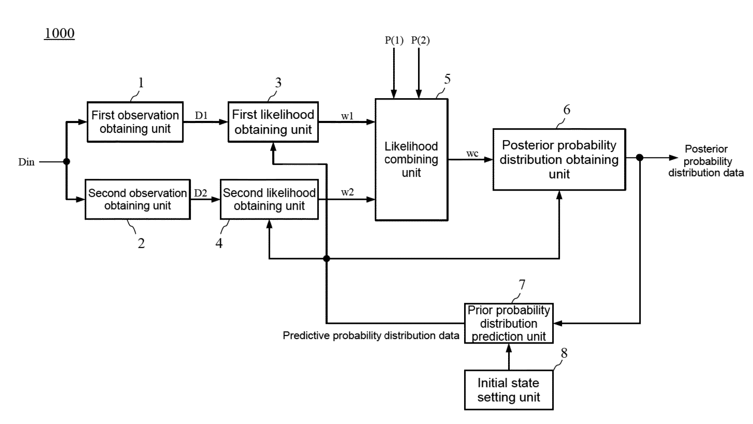
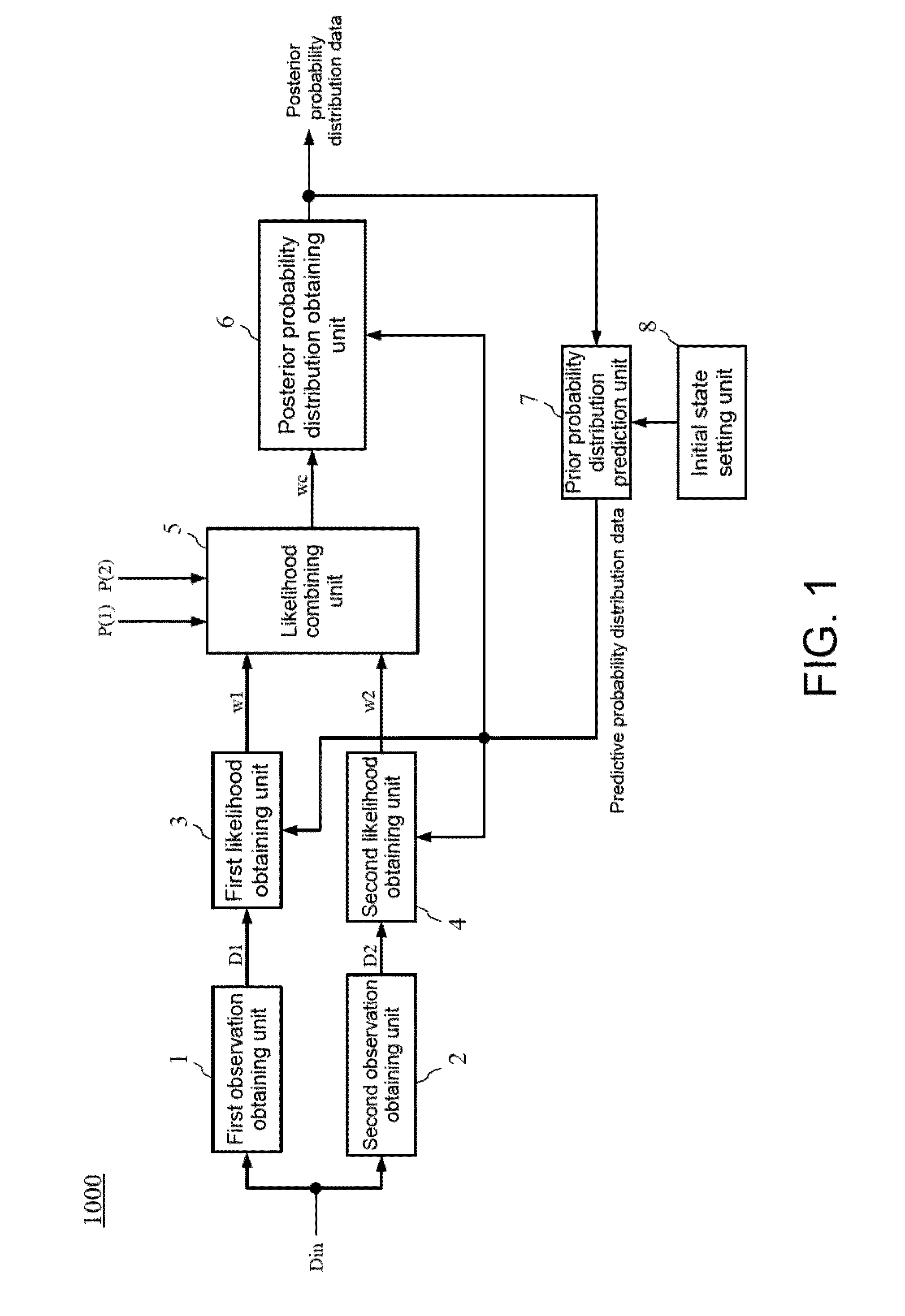
[0060]FIG. 1 is a schematic block diagram of a state estimation apparatus 1000 according to the first embodiment.

[0061]As shown in FIG. 1, the state estimation apparatus 1000 includes a first observation obtaining unit 1, a second observation obtaining unit 2, a first likelihood obtaining unit 3, a second likelihood obtaining unit 4, a likelihood combining unit 5, a posterior probability distribution obtaining unit 6, a prior probability distribution prediction unit 7, and an initial state setting unit 8.

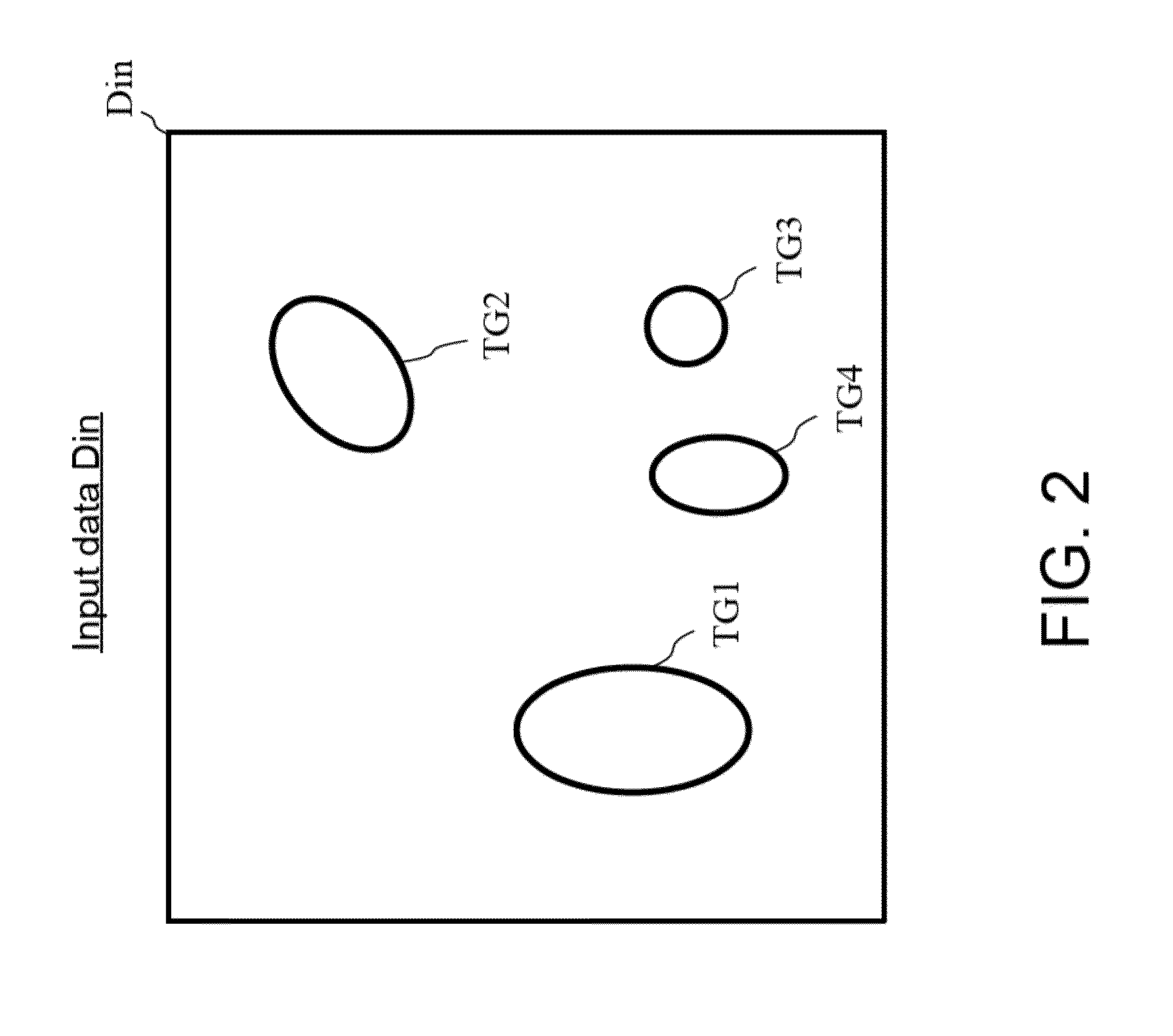
[0062]The first observation obtaining unit 1 receives input data Din. The first observation obtaining unit 1 obtains first observation data D1 from the input data Din, and outputs the obtained first observation data D1 to the first likelihood obtaining unit 3. The input data Din obtained by the first observation obtaining unit 1 is, for example, an image captured ...

second embodiment

[0148]A second embodiment will now be described.

[0149]In the present embodiment, the components that are the same as in the above embodiment and modification are given the same reference numerals as those components, and will not be described in detail.

2.1 Structure of State Estimation Apparatus

[0150]FIG. 8 is a schematic block diagram of a state estimation apparatus 2000 according to the second embodiment.

[0151]As shown in FIG. 8, the state estimation apparatus 2000 of the second embodiment differs from the state estimation apparatus 1000A according to the first modification of the first embodiment in that the first observation obtaining unit 1 and the second observation obtaining unit 2 are replaced with a first observation obtaining unit 1A and a second observation obtaining unit 2A, and the state estimation apparatus 2000 additionally includes a first reliability obtaining unit 9 and a second reliability obtaining unit 10.

[0152]The first observation obtaining unit 1A obtains dat...

first modification

[0225]A first modification of the second embodiment will now be described.

[0226]In this modification, the components that are the same as in the above embodiment will not be described in detail.

[0227]In a state estimation apparatus 2000A of this modification, the first observation obtaining unit 1A receives a signal (data) Din1 obtained by an imaging apparatus including a visible light image sensor, whereas the second observation obtaining unit 2A receives a signal (data) Din2 obtained by an imaging apparatus including an infrared image sensor.

[0228]FIG. 16 is a schematic block diagram of the state estimation apparatus 2000A according to the first modification of the second embodiment.

[0229]As shown in FIG. 16, the state estimation apparatus 2000A of this modification differs from the state estimation apparatus 2000 according to the second embodiment in that the state estimation apparatus 2000A additionally includes a sensor unit S1, and the likelihood combining unit 5 is replaced w...


PUM


Abstract

A state estimation apparatus obtains observation data sets for a tracking target object, and estimates an internal state of the object using likelihoods obtained from the observation data sets and the reliability of each observation data set. A first observation obtaining unit obtains first observation data. A second observation obtaining unit obtains second observation data. A first likelihood obtaining unit obtains a first likelihood based on the first observation data. A second likelihood obtaining unit obtains a second likelihood based on the second observation data. A likelihood combining unit obtains a combined likelihood based on the first and second likelihoods, first reliability data indicating the reliability of the first observation data, and second reliability data indicating the reliability of the second observation data. A posterior probability distribution obtaining unit obtains posterior probability distribution data indicating a probability distribution of the internal state of the observation target at current time t from the combined likelihood and predictive probability distribution data.

Description

[0001]This application claims priority to Japanese Patent Application No. 2014-250985 filed on Dec. 11, 2014, the entire disclosure of which is hereby incorporated herein by reference (IBR).BACKGROUND OF THE INVENTION[0002]1. Field of the Invention[0003]The present invention relates to a technique for estimating the state of an observable event using time-series filtering, and particularly to, for example, a technique for tracking objects in a moving image using time-series filtering.[0004]2. Description of the Background Art[0005]Techniques for estimating the internal state of an observation target, changing from moment to moment, may use time-series filtering. With a state vector xt indicating the internal state of an object at time t and an observation vector yt indicating a feature observed at time t, time-series filtering enables an internal state xt of a directly unobservable object to be estimated using the observation vector yt obtained through observation.[0006]More specifi...

Claims


Application Information

Patent Timeline
IPC IPC(8): G06T7/20H04N7/18
CPCH04N7/181G06T7/2093G06T2207/10016G06T2207/20076G06T2207/30244G06T7/277G06T7/292
Inventor HASEGAWA, HIROMUIKOMA, NORIKAZU
Owner MEGACHIPS
Why Eureka
Try Eureka