Volume limiting bodily fluid drainage system

a bodily fluid and volume limitation technology, applied in the field of medical drainage systems, can solve the problems of blockage of the flow of csf, coma, or even death, accumulation of csf in the ventricles, and rise of icp

Active Publication Date: 2012-07-17
INTEGRA LIFESCI +1
View PDF27 Cites 8 Cited by
  • Summary
  • Abstract
  • Description
  • Claims
  • Application Information

AI Technical Summary

Benefits of technology

[0019]In accordance with further aspects, the bodily fluid drainage system further comprises a seal plug mounted on the float member below the inflow port and moving with the float member, located so as to allow flow of bodily fluid through the inflow port into the collection chamber in the open configuration when the chamber has no fluid in it and closes the inflow port so as to prevent the flow of bodily fluid through the inflow port into the collection chamber in the closed configuration when a predetermined volume of bodily fluid collects in the collection chamber.
[0021]Further aspects in accordance with the invention comprise the float member including a top portion at which is disposed a hollow chimney extension having a pressure equalization hole at a top surface, the pressure equalization hole configured to communicate with an interior of the float member to equalize interior pressure with outside pressure wherein a length of the hollow chimney extension is selected to place the equalization hole high up in the collection chamber above the collected fluid level thereby preventing the collected fluid from entering the float member lumen under normal operating conditions. The pressure equalization hole has a diameter that is selected to be small in size so that it inhibits the movement of the bodily fluid through the equalization hole to thereby avoid changes in buoyancy of the float member.
[0022]Additional more detailed aspects include a seal plug mounted on a top portion of the float member below the inflow port and moving with the float member, and located so as to allow flow of bodily fluid through the inflow port into the collection chamber in the open configuration when the chamber has no fluid in it and closes the inflow port so as to prevent the flow of bodily fluid through the inflow port into the collection chamber in the closed configuration when a predetermined volume of bodily fluid collects in the collection chamber, wherein the seal plug is positioned on the float member between the chimney extension and the hinge. In another aspect, the seal plug is positioned adjacent the hinge.
[0032]In other more detailed aspects, the bodily fluid drainage system comprises a seal plug mounted on the float member below the first vent port and moving with the float member, the seal plug being located so as to allow air to flow out of the first vent port from the collection chamber in the open configuration when the chamber has no fluid in it and closes the first vent port so as to prevent the flow of air out of the collection chamber in the closed configuration when a predetermined volume of bodily fluid collects in the collection chamber.

Problems solved by technology

A rise in intracranial pressure (ICP) from the accumulation of excess amounts of CSF may lead to headaches, coma, or even death.
Blockage of the flow of CSF may cause accumulation of CSF in the ventricles and a rise in ICP.
Such blockages to the flow of CSF may result from tumors or may be associated with subarachnoid hemorrhage, for example when an intracranial aneurysm ruptures.
Removal of too much CSF, or “overdrainage,” by these catheters is also not desirable.
Excessive CSF drainage by ventricular or lumbar catheters may result in severe headaches or collapse of the ventricular cavities.
Excessive collapse of the ventricles may also cause shifts of the brain and cerebral arteries, thereby causing re-rupture of an intracranial aneurysm.
CSF is typically sterile when drained from the patient and contamination of the CSF by microbes may have adverse consequences on the patient.
Overdrainage of CSF from the patient can result in “overfilling” of the drainage bag which is a condition wherein too much CSF fluid fills the drainage bag.
Overfilling a drainage bag or container may cause further problems, including leakage of the fluid from the system and infection through the pathway provided by the leaking fluid.
Overfilling may also cause undesirable CSF contact with portions of a drainage system that function best when kept dry, for example an hydrophobic filter.
CSF typically includes glucose and other proteinaceous substances and should CSF come into contact with a vent filter, it may adhere to the filter thereby making the passage of air through the filter in either direction difficult or impossible.
The container would then be rendered useless and must be replaced.
Such monitoring requires the personal attention and time from clinicians who are probably already quite busy.
Flow may unexpectedly increase if the level of the system is lowered in relation to the level of the catheter entering the patient.
For example, an uncooperative or confused patient may sit up in bed, thereby changing his position farther above where the system has been positioned and result in an increased flow rate of CSF into the drainage and collection system.
These systems may further result in overdrainage when the collection container is inadvertently positioned too low and / or drainage goes unnoticed by the busy clinician for some time.
A more serious risk can occur when a displaced collection container falls or is compressed thereby forcing a large volume of the collected CSF back into the patient.
Flow of CSF through a drain may also suddenly increase with coughing or sneezing by the patient.
Overfilling may occur if a busy clinician does not empty the collection chamber of CSF before it fills to undesirable levels.
Such a system does not account for overfilling.
This system also does not prevent overfilling and requires manual monitoring.
The above devices known in the art all have disadvantages when applied to clinical use for measured CSF drainage.
For example, prior art devices do not provide an automatic limitation of flow, or they are complicated and expensive to manufacture, fill from the bottom, clog easily when exposed to proteinaceous fluids, or may hamper the free flow of CSF between a patient and a collection container.

Method used


Image

  • Volume limiting bodily fluid drainage system
  • Volume limiting bodily fluid drainage system
  • Volume limiting bodily fluid drainage system

Examples


Embodiment Construction

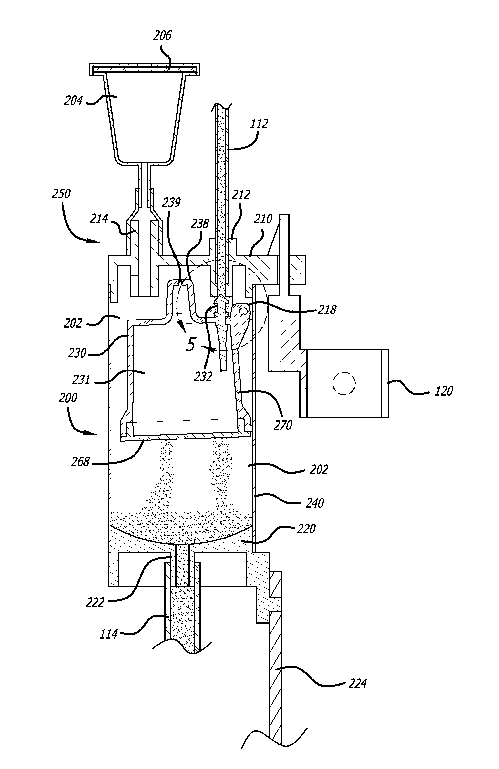
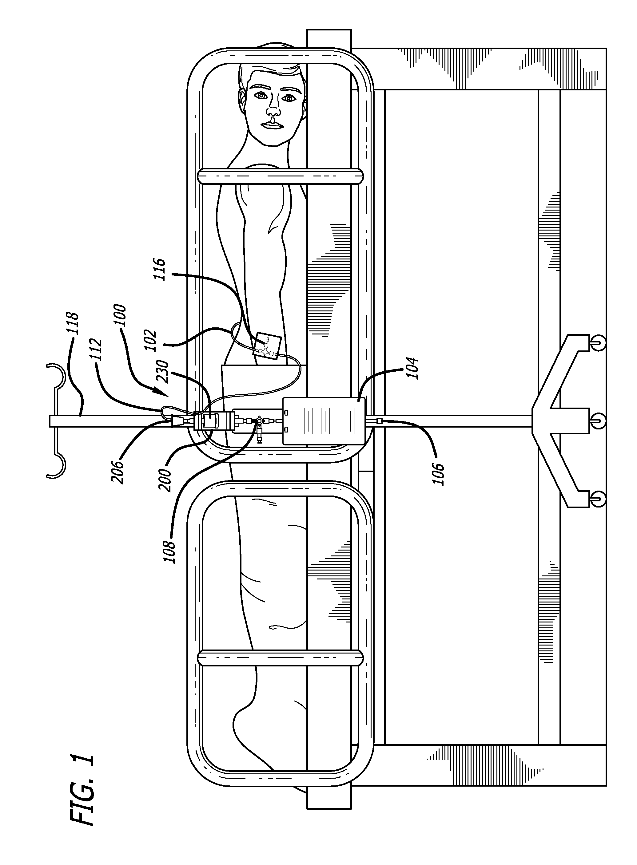
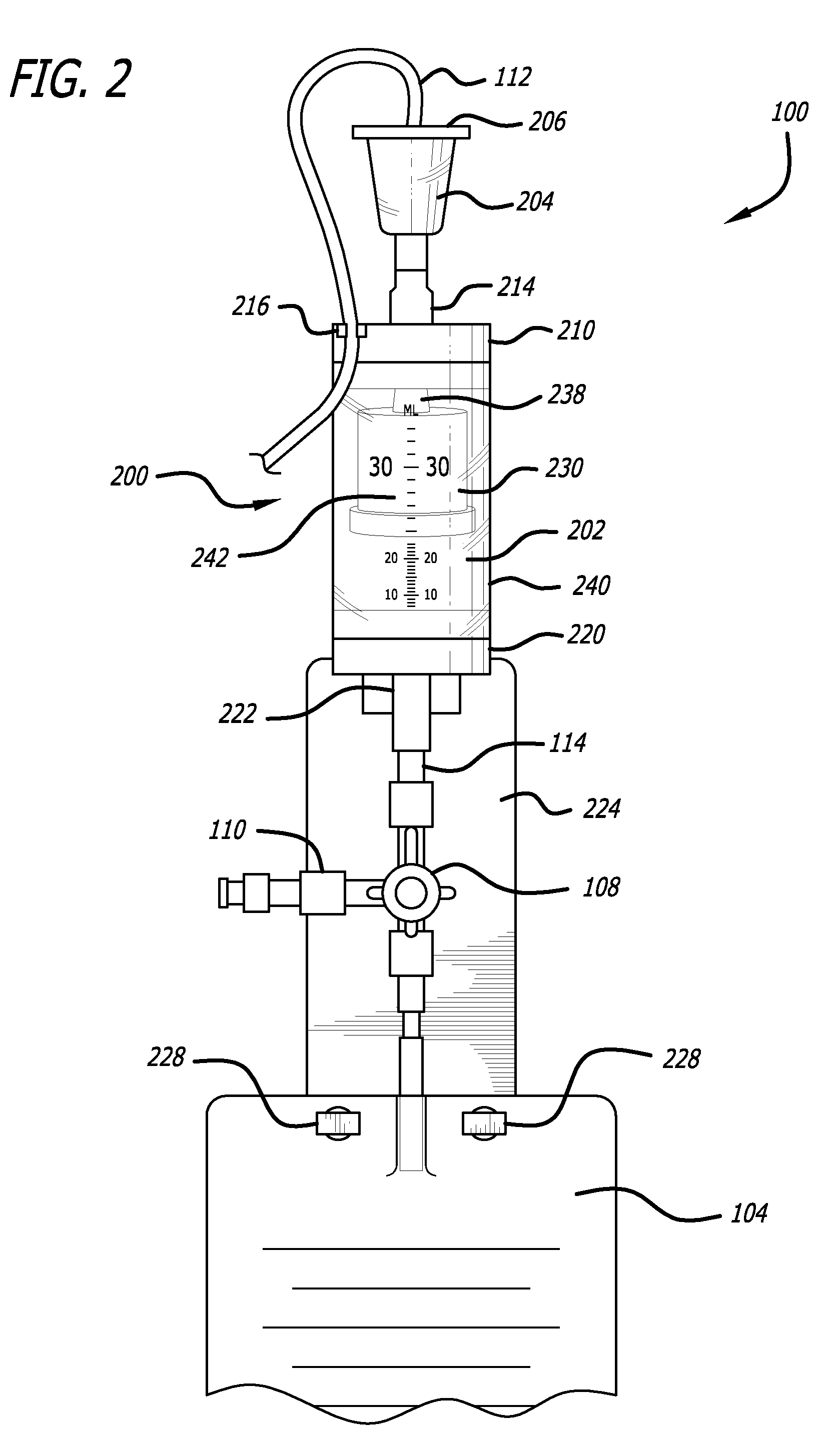
[0046]Referring now in more detail to the exemplary drawings for purposes of illustrating embodiments of the invention, wherein like reference numerals designate corresponding or like elements among the several views, an embodiment of a body fluid drainage system for volume limited drainage of a body fluid, such as cerebrospinal fluid (CSF), is illustrated in FIGS. 1-8 in accordance with aspects of the present invention.

[0047]Referring first to FIG. 1, one embodiment of the fluid drainage system 100 of the present invention is adapted to drain cerebro-spinal fluid (CSF) from the lumbar subarachnoid space of a patient. The drainage system includes a catheter 102 adapted to be inserted into the lumbar subarachnoid space through the low back of a patient to be treated. In another embodiment, the catheter may be inserted into the lateral ventricles of the patient to be treated to drain CSF from the brain. In yet another embodiment, bodily fluids from other anatomical locations or body c...


PUM

PropertyMeasurementUnit
volumeaaaaaaaaaa
volumeaaaaaaaaaa
volumeaaaaaaaaaa

Abstract

A system and method are disclosed for automatically limiting the drainage of a bodily fluid such as cerebrospinal fluid (CSF) from a patient into a collection chamber. The collection chamber includes a vent having an hydrophobic filter for the passage of air to facilitate the movement of CSF yet to maintain a closed system. The system includes a buoyant float hingedly connected with the top of the collection chamber in one embodiment. When fluid rises in the collection chamber to a predetermined volume, buoyant force raises the float and causes a seal plug mounted on top of the float to seal one of an inflow port or a vent port. The float is limited to pivoting movement in one plane and to a certain angle within that plane. The system and method avoid overdrainage of CSF from the patient and overfilling of the collection chamber.

Description

BACKGROUND OF THE INVENTION[0001]1. Field of the Invention[0002]The present invention relates generally to medical drainage systems configured to remove bodily fluids from a patient, and more particularly, to a medical drainage system to controllably remove bodily fluids, such as cerebrospinal fluid (CSF), from a patient.[0003]2. Brief Description of Related Art[0004]Cerebrospinal fluid (CSF) is normally a clear watery body fluid that is formed by the human body in the ventricular cavities located within the brain. The CSF flows from the lateral ventricles and third ventricle to the fourth ventricle. Thereafter, the CSF under normal conditions exits the fourth ventricle to flow into the subarachnoid spaces that surround the outside of the brain, the spinal cord, and the lumbosacral nerve roots. The CSF under normal conditions forms at a rate of about 400-500 milliliters per day and is absorbed by the body at the exact same rate, such that the equilibrium between the formation of CSF...

Claims


Application Information

Patent Timeline
Patent Type & Authority Patents(United States)
IPC IPC(8): A61M1/00
CPCA61M1/0049A61M1/005A61M2202/0464A61M1/78A61M1/782Y10T137/3109
Inventor HOFFMAN, BRIANMCDERMOTT, MICHAELCHANG, WILLIAM R.CLASEN, ERIC SCOTT
Owner INTEGRA LIFESCI
Why Eureka
Try Eureka