Electronic device
a technology of electronic devices and components, applied in the field of electronic devices, can solve the problems of increasing manufacturing costs
- Summary
- Abstract
- Description
- Claims
- Application Information
AI Technical Summary
Benefits of technology
Problems solved by technology
Method used
Image
Examples
first embodiment
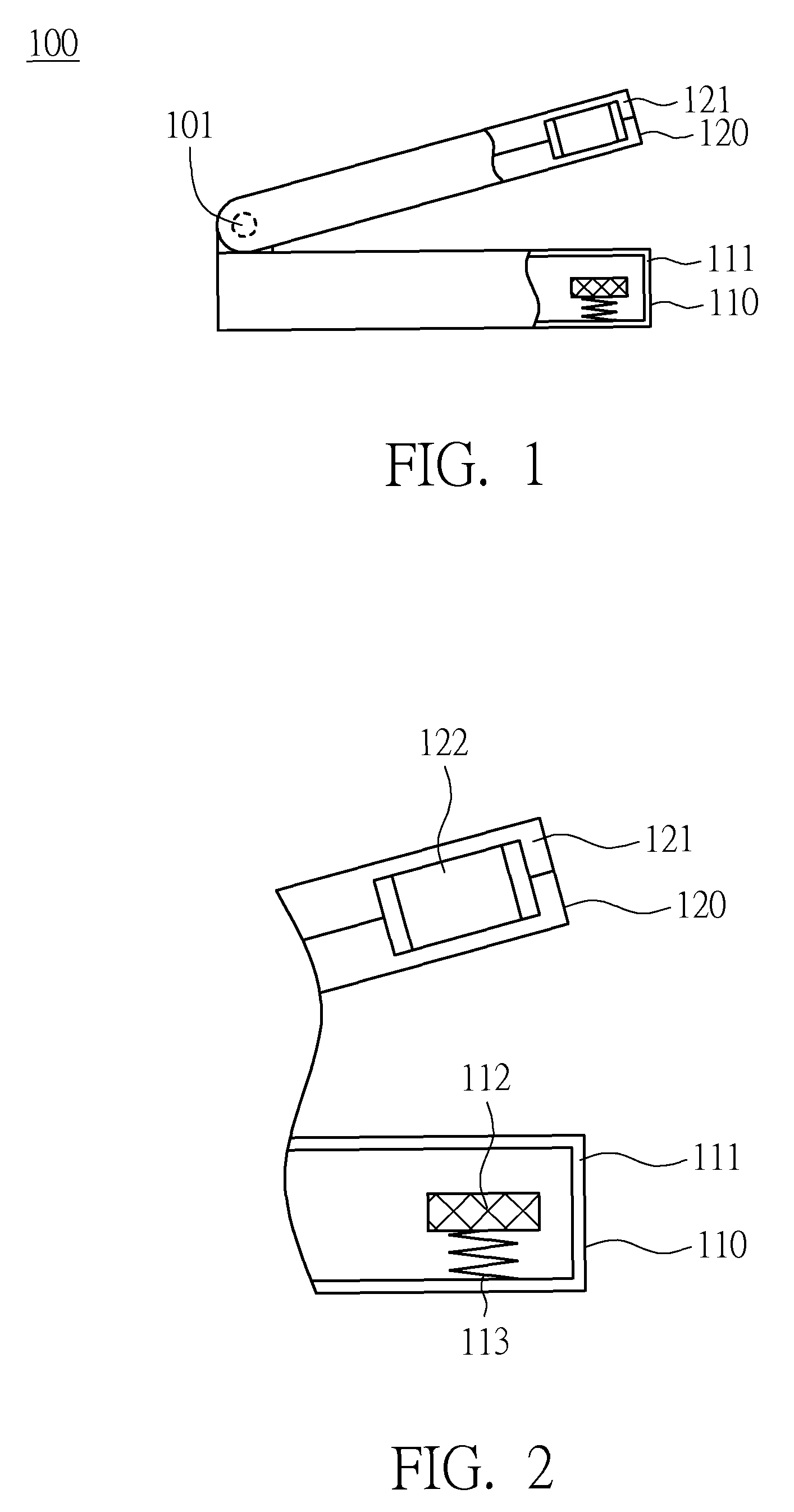
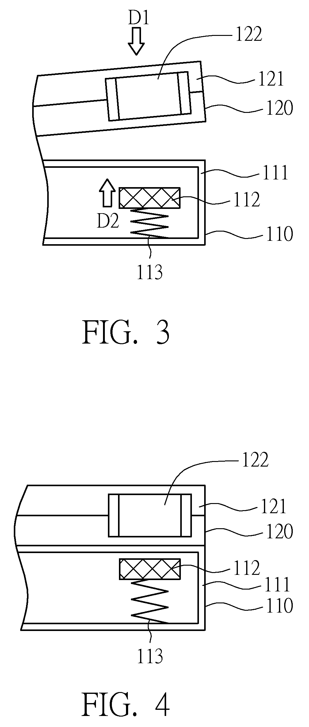
[0034]FIG. 1 is a diagram showing an electronic device 100 according to a first embodiment of the present invention in a non-closed position. FIG. 2 shows a partially enlarged view of the electronic device 100 in FIG. 1 in the non-closed position. The electronic device 100 is, for example, a smart phone, a PDA phone, a laptop computer, an ultra mobile PC (UMPC) or a portable electronic device. As shown in FIG. 1, the electronic device 100 includes a first main body 110 and a second main body 120. The first main body 110 includes a first housing 111, and the second main body 120 includes a second housing 121. The second housing 121 is pivotally connected with the first housing 111. In the present embodiment, the second housing 121 is pivotally connected with the first housing 111 through a pivot 101 so that the second housing 121 is able to rotate relative to the first housing 111. As shown in FIG. 2, the first main body 110 further includes a first magnetic member 112 and a first el...
second embodiment
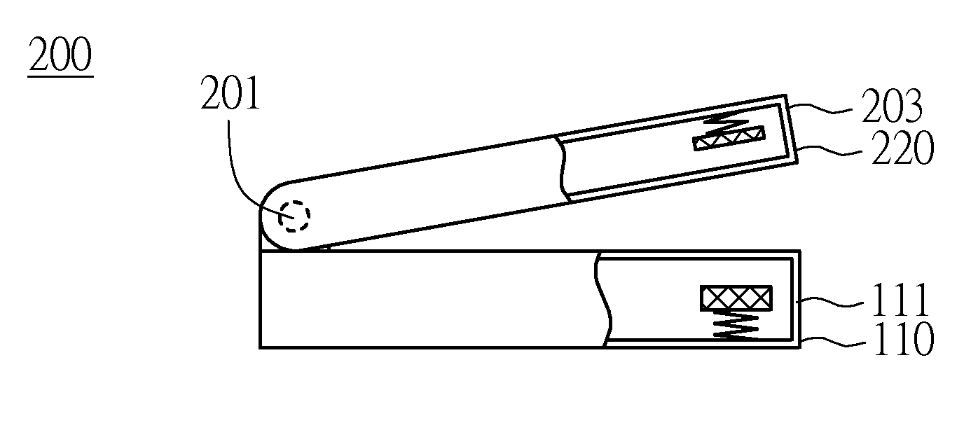
[0043]FIG. 8 is a diagram showing the electronic device 200 according to a second embodiment of the present invention in a non-closed position. FIG. 9 shows a partially enlarged view of the electronic device 200 in FIG. 8 in the non-closed position. The difference between the present embodiment and the first embodiment is that the second main body 220 further includes a second elastic member 202. As shown in FIG. 8, the electronic device 200 includes a first main body 110 and a second main body 220. The second main body 220 can cover the first main body 110. The first main body 110 includes a first housing 111, and the second main body 220 includes a second housing 203. The second housing 203 is pivotally connected with the first housing 111. The second housing 203 is connected with the first housing 111 through the pivot 201, so that the second housing 203 is able to rotate relative to the first housing 111. In FIG. 9, preferably the first main body 110 further includes a first mag...
third embodiment
[0051]FIG. 15 is a diagram showing an electronic device 300 according to a third embodiment of the present invention having a first main body 310 separated from a second main body 320. The difference between the present embodiment and the first embodiment is that the second main body 320 can be detached from the first main body 310. The first main body 310 includes a first housing 311, a first magnetic member 312 and a first elastic member 313. The first elastic member 313 is disposed within the first housing 311 and connects with the first magnetic member 312 and the first housing 311, so that the first magnetic member 312 is floatable within the first housing 311. The second main body 320 includes a second housing 321 and a second magnetic member 322. The second magnetic member 322 is disposed within the second housing 321. The first magnetic member 312 is, for example a magnet. Preferably, the second magnetic member 322 is made of a magnetic material or is a magnet, for generatin...
PUM
 Abstract
Description
Claims
Application Information
 - R&D
- Intellectual Property
- Life Sciences
- Materials
- Tech Scout
- Unparalleled Data Quality
- Higher Quality Content
- 60% Fewer Hallucinations
Browse by: Latest US Patents, China's latest patents, Technical Efficacy Thesaurus, Application Domain, Technology Topic, Popular Technical Reports.
© 2025 PatSnap. All rights reserved.Legal|Privacy policy|Modern Slavery Act Transparency Statement|Sitemap|About US| Contact US: help@patsnap.com


