Device for delivering and/or spraying flowable media, especially fluids

a flowable media and fluid technology, applied in the direction of positive displacement liquid engines, piston pumps, magnets, etc., can solve the problems of increasing the injection system requirements of these internal elements, entail additional costs not only for the larger elements but also for the larger elements, and achieve the effect of increasing the efficiency of the device in accordance with the invention, increasing the energy input, and small structural spa

Inactive Publication Date: 2006-08-22
BRP US
View PDF13 Cites 20 Cited by
  • Summary
  • Abstract
  • Description
  • Claims
  • Application Information

AI Technical Summary

Benefits of technology

[0008]This results in increasing demands on the injection systems of these internal combustion engines with respect to the flow rates per working cycle and with respect to the volume flow (i.e., fluid flow rate per unit of time).
[0009]This increased flow rate per working cycle and the increased volume flow can be achieved, for example, by enlarging the electromagnets, though these then also have a higher electrical power consumption. But this entails additional costs not only for the larger elements but also, and above all, for generators and control circuits for the electromagnets that are more powerful.
[0010]The task of the invention is to produce a device to convey and / or spray free-flowing media, in particular fluids, that guarantees a higher flow rate per working cycle and a higher volume flow of the sprayed or conveyed fluid at a certain or given electrical energy supply and in particular a certain or given structural size, in other words is improved with respect to the efficiency.
[0016]Within the scope of the invention, the effect is exploited whereby an enlargement of the working gap plane between one armature and its magnetically corresponding yoke means that a greater amount of energy can be transmitted from the magnetic field provided by a coil to the armature device.
[0017]In accordance with the invention, an enlargement of the working gap plane is achieved by a very simple method, whereby a magnetic series connection of at least two armature elements together with their respective corresponding yoke elements is planned. Accordingly, an armature device is to be provided, for example, that bears a multiple of, i.e. at least two, axially spaced armature elements on an armature carrier, e.g. a delivery plunger tube.
[0021]With a device to convey and / or spray free-flowing media, in particular fluids, in accordance with the invention, it is advantageous that, with a given electrical energy supply, the static magnetic force on the armature device is much higher than the state-of-the-art and, thus, the work performed by the armature device along its stroke path is much greater. In this respect, the energy transmitted by the armature device to the medium to be conveyed or sprayed and, thus, the efficiency of the device in accordance with the invention, is significantly increased. A device in accordance with the invention requires only a small structural space on account of the axially serial arrangement of the armature elements in a magnetic serial connection.

Problems solved by technology

This results in increasing demands on the injection systems of these internal combustion engines with respect to the flow rates per working cycle and with respect to the volume flow (i.e., fluid flow rate per unit of time).
This increased flow rate per working cycle and the increased volume flow can be achieved, for example, by enlarging the electromagnets, though these then also have a higher electrical power consumption.
But this entails additional costs not only for the larger elements but also, and above all, for generators and control circuits for the electromagnets that are more powerful.

Method used


Image

  • Device for delivering and/or spraying flowable media, especially fluids
  • Device for delivering and/or spraying flowable media, especially fluids
  • Device for delivering and/or spraying flowable media, especially fluids

Examples


Embodiment Construction

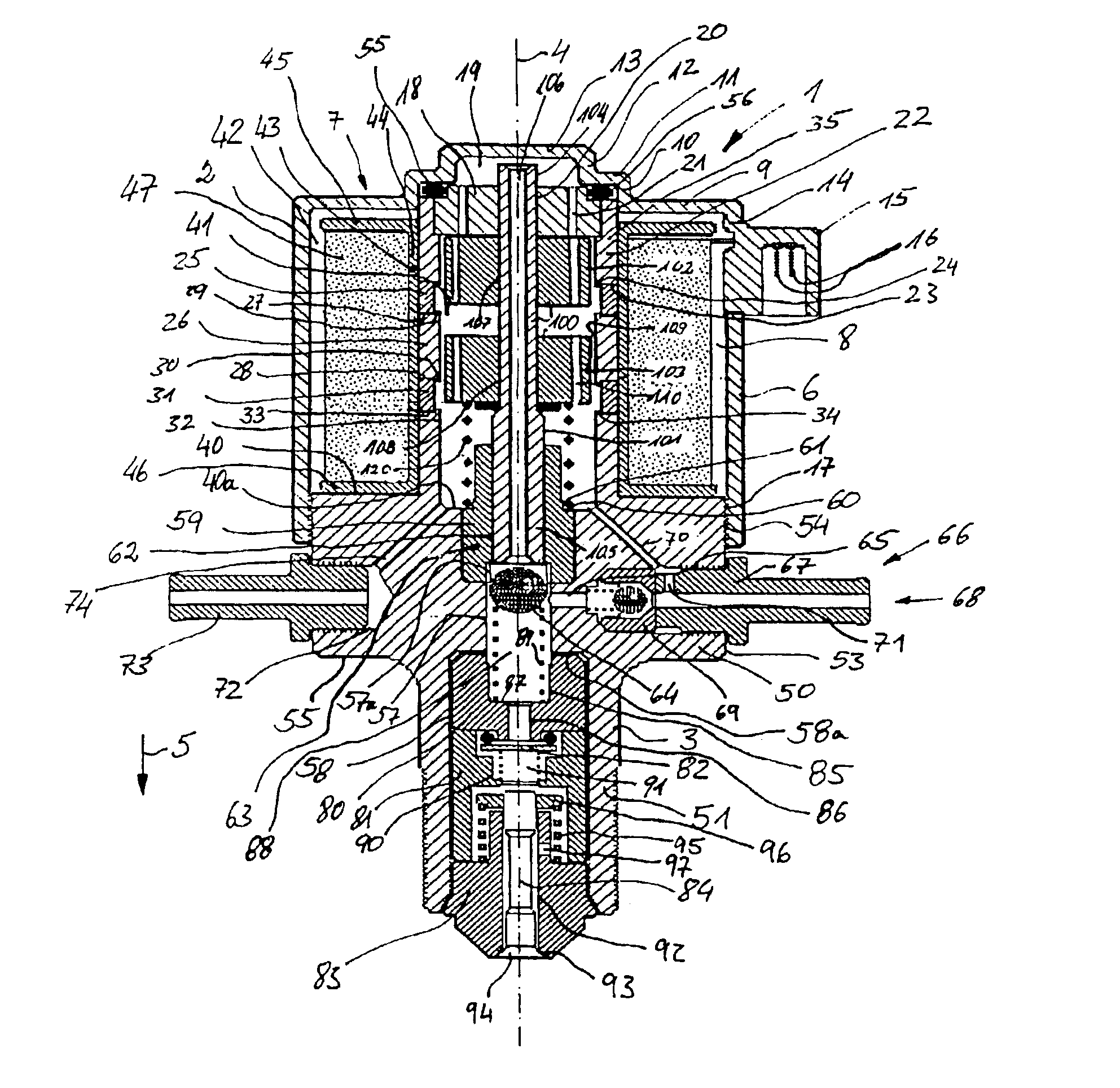
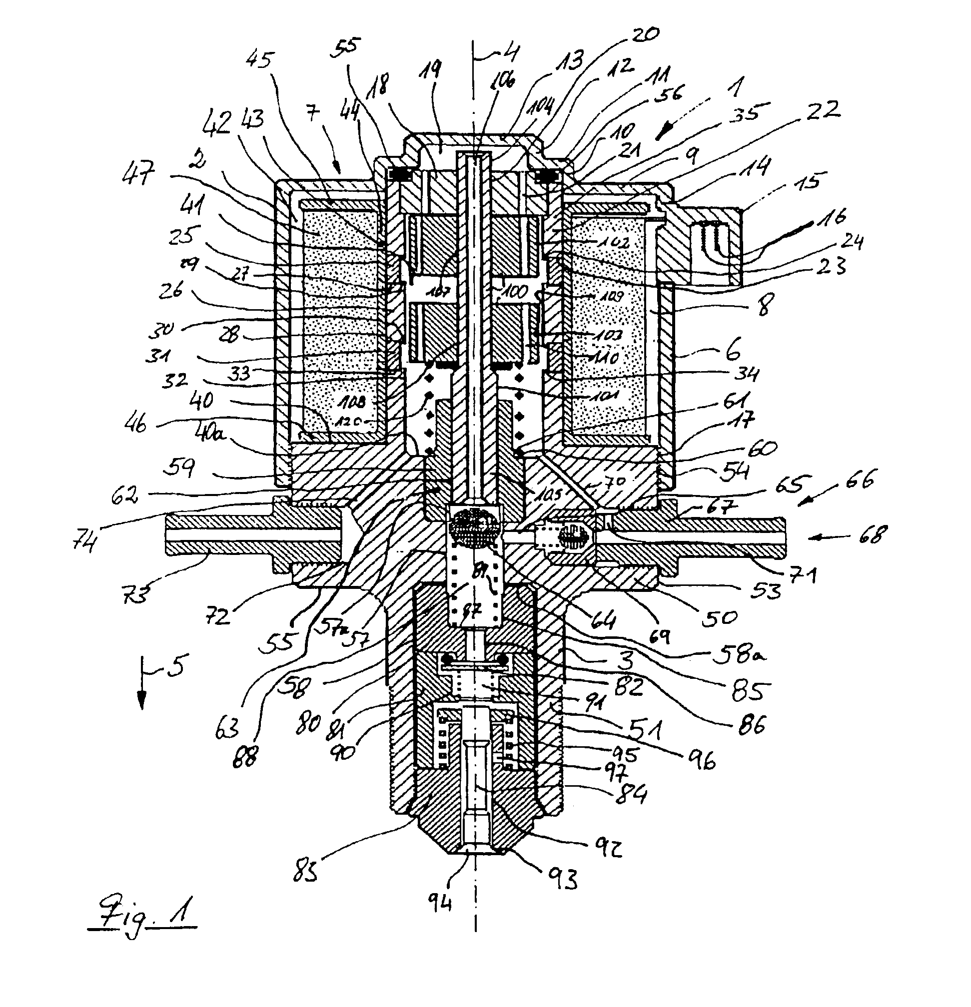
[0027]The preferred variant of the device 1 in accordance with the invention shown works in accordance with the solid body energy storage principle and shows a pot-shaped drive housing 2 and a pump housing 3 that closes an open end of the pot-shaped drive housing 2. The drive housing 2 and the pump housing 3 are essentially rotationally symmetrical bodies and have a common central longitudinal axis 4. The pump housing 3 is arranged upstream from the drive housing 2 in a direction of delivery 5 of the medium to be conveyed or sprayed.

[0028]The drive housing 2 has a thin-walled, cylinder jacket-shaped outside wall 6 and a thin-walled base wall 7 that closes one end of the drive housing 2 so that a drive housing inner space 8 is limited. The base wall 7 has two steps radial to the central longitudinal axis 4. The base wall 7 has a first annular face wall 9 running radially from the outside to the inside, a first annular stepped wall 10 running coaxially to the outside wall 6, a second ...


PUM

PropertyMeasurementUnit
magnetic fluxaaaaaaaaaa
distanceaaaaaaaaaa
distancesaaaaaaaaaa

Abstract

The invention concerns a device to convey and / or spray free-flowing media, in particular fluids, which works in accordance with the energy storage principle and is designed as an electromagnetically-powered reciprocating pump with at least one armature device as a drive element, whereby the armature device includes at least two armature elements and the armature elements are assigned magnetically corresponding yoke elements.

Description

[0001]This is a National Phase entry from PCT Patent Application Serial No. PCT / EP00 / 07210, filed on Jul. 26, 2000, which designated the United States. The PCT Patent Application was not published under PCT Article 21(2) in English. This application relies for priority on German Patent Application No. 199 37 988.2, filed on Aug. 11, 1999. Both applications are incorporated herein by reference.FIELD OF THE INVENTION[0002]The invention concerns a device to convey and / or spray free-flowing media, in particular fluids, which works in accordance with the energy storage principle and is designed as an electromagnetically powered reciprocating pump.DESCRIPTION OF THE RELATED ART[0003]A device of this kind is familiar for example from WO 96 / 34196. These injection devices work according to the solid body energy storage principle and have an armature space enclosed by an armature cylinder in which an armature device, acting as the drive device, is borne in such a manner that its can move axia...

Claims


Application Information

Patent Timeline
Patent Type & Authority Patents(United States)
IPC IPC(8): F02M51/00B05B9/04F02M51/04F02M51/06F02M51/08F02M57/02F02M61/08F04B17/04F16K31/06H01F7/16H02K33/02
CPCB05B9/0413F02M51/04H02K33/02F02M61/08F04B17/046F02M57/027
Inventor HELLMICH, WOLFRAMPETER, KLAUS-JURGENKOTTER, ROBERTZHANG, LIANG
Owner BRP US
Why Eureka
Try Eureka