Measuring cable travel sensor

a technology of cable travel and travel sensor, which is applied in the direction of measuring wheels, instruments, elevators, etc., can solve the problems of falsification of measurement, additional difficulty, and suffers of cable travel sensors of this kind

Inactive Publication Date: 2003-04-08
ASM AUTOMATION SENSORIK MESSTECHN GMBH
View PDF8 Cites 17 Cited by
  • Summary
  • Abstract
  • Description
  • Claims
  • Application Information

AI Technical Summary

Benefits of technology

Referring now to FIG. 8c, the structure therein differs from that shown in FIG. 8b in that, instead of the shoe 114 in FIG. 8a, over the first quadrant of the measuring cable 15 to be wound on to the cable drum 5, two or even more sliding rollers or contact rollers 130 which are supported in the housing 104 bear from the outside of the wound-on measuring cable 15 on the drum against the measuring cable, and thus, by contact with the outside surface of the measuring cable, prevent the measuring cable from lifting away from the external periphery of the cable drum 5.

Problems solved by technology

In that respect there is an additional difficulty insofar as such measuring cable travel sensors often have to be used in an adverse environment, for example involving a high level of fouling and contamination.
However, measuring cable travel sensors of that kind suffer from two different difficulties which however are interrelated in terms of their origin, more specifically as follows:
Nonetheless, when the cable is wound on to the drum at very high speed, it can happen under some circumstances that the measuring cable can climb up or fly out, that is to say adopt a position at a spacing relative to the external peripheral surface of the cable winding drum, and in that case for example the measuring cable will jump over the first layer of turns already on the cable drum to form a second layer there over, being a phenomenon which is undesirable as it grossly falsifies the measurement result.
Attempts have already been made to prevent the measuring cable from climbing up over the previous turns already wound on the cable drum, for example by mechanical guide and tracking devices, distribution devices and so forth, but that tends to result in undesirable side effects such as wear, an increase in the winding force and the like, because of the mechanical friction involved.
Another detrimental effect of the high level of cable drum biassing is that, in the situation where the free end of the cable moves towards the cable drum more quickly than the cable drum can wind the measuring cable on to it or in the situation where the free end of the cable becomes detached from the component whose travel is to be measured so that the cable moves towards the cable entrance and into the travel sensor housing completely without any retardation force being applied to the cable, as a result the spring-biassed cable drum speeds up to very high speeds of rotation and at the end of the winding-on movement the free end of the cable which is usually of greater thickness and which is equipped with a fixing device for example using an eye strikes at very high speed against the cable entrance structure which is of smaller size in relation thereto.
That can result in damage or even tearing of the measuring cable or can disrupt the connection between the measuring cable and its fixing device on the free end of the cable, and so forth.
That would also remove the compulsion for the provision of at least a pair of braking magnets on the cable drum, as a single magnet results in a cable drum unbalance, and that arrangement also makes available more space for example for fitting a magnet holder for adjustability of the air gap.

Method used


Image

  • Measuring cable travel sensor
  • Measuring cable travel sensor
  • Measuring cable travel sensor

Examples


Embodiment Construction

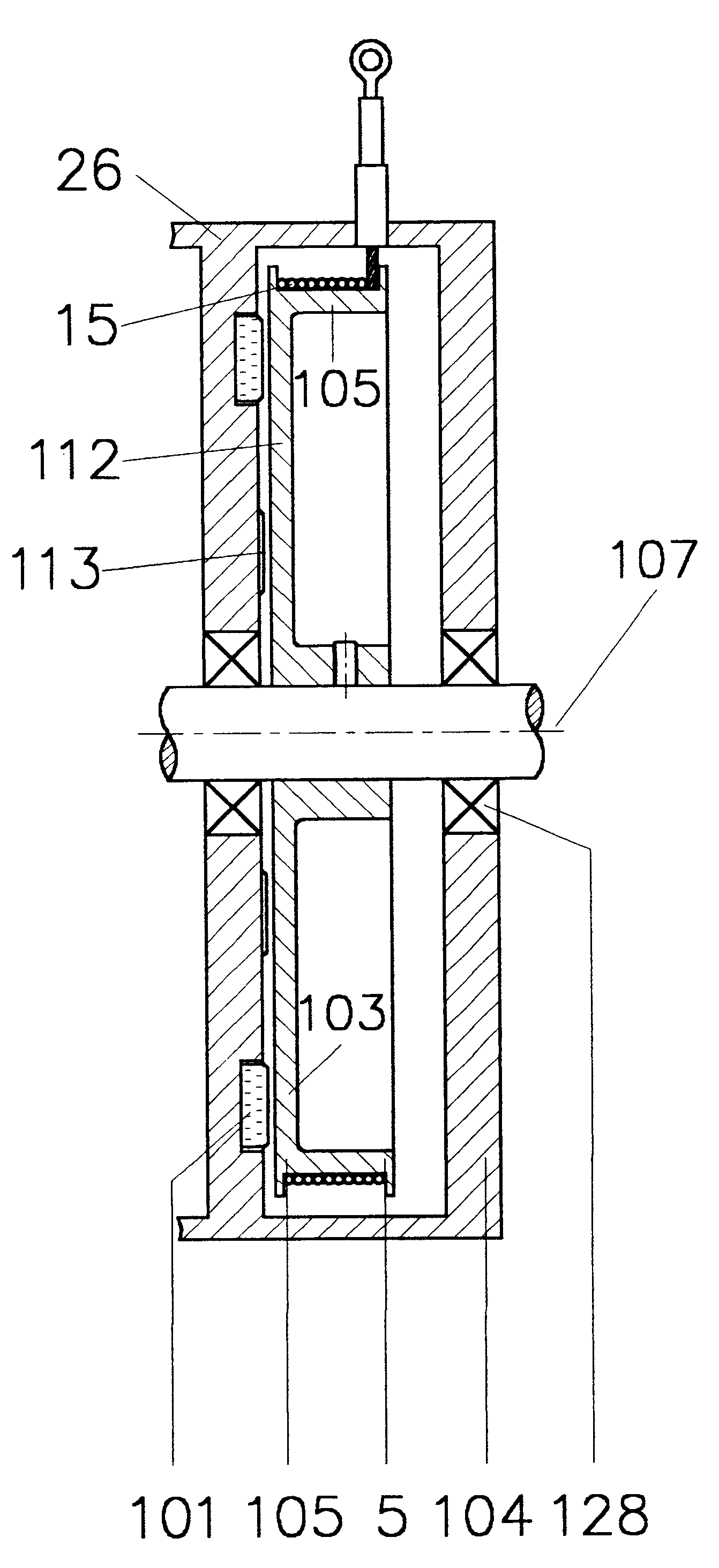
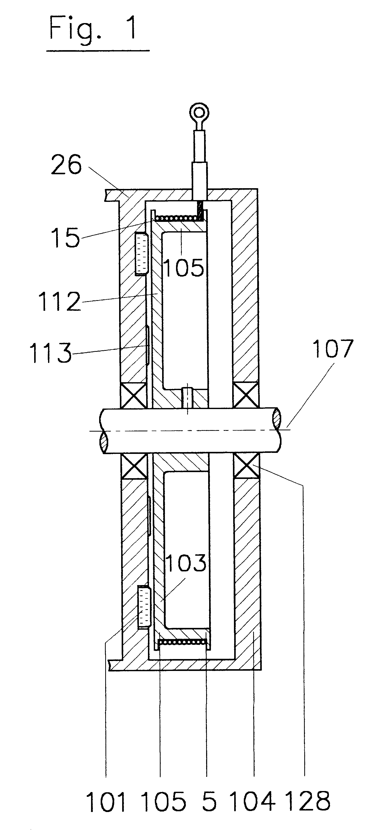
Reference will now be made generally to FIGS. 1 and 2 which each show a respective embodiment of a measuring cable travel sensor according to the invention, comprising a rotatable cable drum 5 which is suitably fixed on a rotatable shaft and which can thus rotate about an axis of rotation as indicated at 107 in FIGS. 1 and 2. For that purpose the rotatable shaft is supported by means of bearings 128 in a housing which in the illustrated structure comprises a generally box-shaped, preferably closed profile member 26.

The cable drum 5 comprises a winding cylinder 105 with an external peripheral winding surface 106 which thus forms the external periphery of the winding cylinder 105. The winding cylinder 105 has radially outwardly facing abutments at each of the two ends thereof for limiting the arrangement of a measuring cable 15 which is to be wound on the winding surface 106. The winding cylinder 105 joins to the hub region of the winding drum 5 in a single step by way of individual s...


PUM


Abstract

A measuring cable travel sensor includes a housing accommodating a measuring cable drum and a rotary spring urging the cable drum in the direction of winding of a measuring cable thereon. At least one braking magnet is arranged either on the cable drum or on the housing to provide for magnetic control of the rotary movement of the cable drum at least in the cable winding-on direction. The cable drum may also carry holding magnets for holding the winding cable into close contact with the peripheral surface of the cable drum. The housing may also have a band extending at least in part around the cable drum for correctly positioning the cable thereon as it is being wound on.

Description

1. Field of the InventionThe invention concerns a measuring cable travel sensor and more particularly a measuring cable travel sensor having a braking device.2. Discussion of the BackgroundMeasuring cable travel sensors occur in many different configurations for example for determining the precise position of a given component which in particular can move over considerable travel distances, for example the cabin of an elevator. A typical measuring cable travel sensor of that kind and for that purpose has a pull element such as a measuring cable which is wound on a cable drum which is biassed in the cable winding-on direction. The free end of the measuring cable is connected to that component whose position is to be determined, for example as mentioned above an elevator cabin. The prestressing force for urging the cable drum in the winding-on direction is produced for example by way of a flat spiral spring which for example is arranged coaxially with respect to the cable drum and is ...

Claims


Application Information

Patent Timeline
Patent Type & Authority Patents(United States)
IPC IPC(8): B65H75/38B65H75/44G01B7/02B66B1/32B66B1/34
CPCB65H75/4442G01B7/026B65H2403/61Y10S33/01B65H2701/35B65H2403/7254
Inventor STEINICH, KLAUS-MANFRED
Owner ASM AUTOMATION SENSORIK MESSTECHN GMBH
Why Eureka
Try Eureka