Systems and methods for guiding conveyance elements

a technology of conveyancing elements and systems, applied in the direction of conveyors, mechanical conveyors, transportation and packaging, etc., can solve the problems of conveyor belts on the surface of the assembly line, assembly line may encounter a problem, assembly line assembly line assembly line assembly line assembly line assembly line assembly line assembly line assembly line assembly line assembly line assembly line assembly line assembly line assembly line assembly line assembly line assembly line assembly line assembly line assembly line assembly line assembly line assembly line assembly line assembly line assembly line assembly line assembly line assembly lin

Inactive Publication Date: 2006-10-17
HABASIT AG
View PDF15 Cites 21 Cited by
  • Summary
  • Abstract
  • Description
  • Claims
  • Application Information

AI Technical Summary

Benefits of technology

[0008]Thus, a need exists for a system and method capable of withstanding unwanted forces applied to a conveyance element in order to hold the conveyance elements in place, flush against the surface of an assembly line (thus preventing lifting in the center or along the edges of the conveyance element from the assembly line) as the assembly line travels linearly or rounds corners in a manufacturing or production environment.
[0009]In satisfaction of these needs, the present invention features an apparatus and methods for holding conveyance elements in place as they move in real time in an environment such as along an assembly line. To increase efficiency and reduce cost, portions of the apparatus and method, such as the conveyance element, may include polymers or polymer-metal blends. This improves reliability, efficiency, and performance.
[0010]In accordance with one aspect of the invention, an apparatus is provided for controlling a conveyance element as it moves along a set path. This apparatus includes a guide defining a path. A chain is coupled to the conveyance element to carry the conveyance element along the path. The conveyance element has two edges corresponding to the two edges of the guide along which the conveyance element is moving. A first rail is also provided along one of the edges of the conveyance element, and thus also along one of the sides of the guide, and a magnetic field is generated that encompasses at least a portion of the apparatus. The magnetic force from the magnetic field holds the conveyance element level against the chain along the location of the conveyance element that is closest to the chain. Preferably, the chain is centered beneath the middle of the conveyance element, so this location is a strip of the conveyance element located directly above the chain. The magnetic field also holds the edge of the conveyance element level against the guide by applying an attractive force between the edge of the conveyance element and the appropriately configured first rail. Preferably, portions of the system may include polymers to reduce cost and weight, and to increase efficiency. In various embodiments, a second rail, also subject to the magnetic force, is provided. The second rail is located in a position along the second edge of the conveyance element, and thus also along one of the edges of the guide, so that the second rail holds the second edge of the conveyance element level against the guide when under the influence of the magnetic force.

Problems solved by technology

Naturally, the assembly of more complicated articles requires a longer or more complicated assembly line.
Due to limitations such as manufacturing plant size, the assembly line is often forced to follow a curved path around the interior of a building.
At high speeds an assembly line may encounter a problem as it rounds a curve.
A conveyor belt on the surface of an assembly line, upon which an article may be placed, may become uneven, as forces such as for example centrifugal forces, act on the surface of the conveyor belt and cause a portion of the conveyor belt to raise up from its support structure.
The same problem may also occur over linear portions of an assembly line.
In other words, a problem exists where the conveyor belt no longer lies flat on the assembly line as it rounds a corner at high speed, or as slack develops along a linear portion.
This raising of the conveyor belt may for example cause a jamming of the assembly line, or may cause the items on the assembly line to fall off the conveyor belt or to shift into an unacceptable position, resulting in a shutting down of the assembly line, and costly repairs, or a delay in the items reaching their end destination.
However, neither of these situations solves the aforementioned tilting or lifting of the conveyor belt in a high speed manufacturing line environment, both may result in damaging the items or the barrier itself, and neither does anything to prevent the items from shifting as a result of the tilt.
The result is increased maintenance cost and reduced performance of the assembly line.
However, this situation requires that the conveyor belt be made of costly and heavy magnetic material and requires an inefficient lubrication system to ensure regular and smooth operation.
Further, such a system may not be used if it is necessary to convey items that may be damaged by contact with metallic surfaces, and the magnets involved must be arranged so that their respective magnetic poles are oppositely orientated, thus increasing the chances of installation error, making it difficult to perform assembly and maintenance, and accordingly increasing the overall production and management costs of the conveyor belt.
Plastic assembly lines still have the shortcoming of oppositely oriented magnetic poles on adjacent magnets, and, importantly, since the attraction force is applied to the center or other single point of the conveyor belt, a level conveyor belt surface around a corner is still not ensured, since the lateral ends, (e.g., edges) of the loading surface still lift from the assembly line when proceeding through a curve at speed, even with the center or the conveyor belt subject to a magnetic field.

Method used


Image

  • Systems and methods for guiding conveyance elements
  • Systems and methods for guiding conveyance elements
  • Systems and methods for guiding conveyance elements

Examples


Embodiment Construction

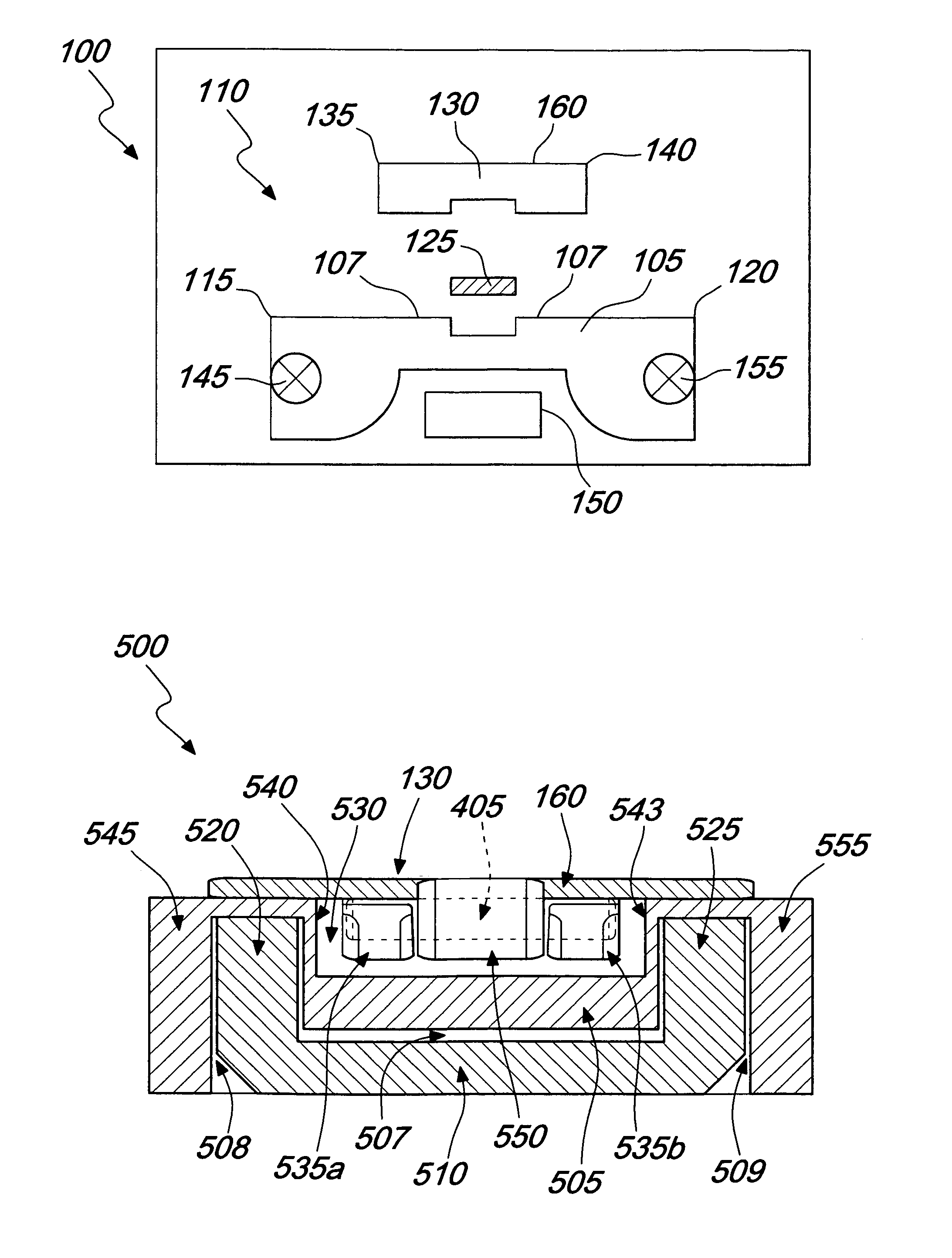
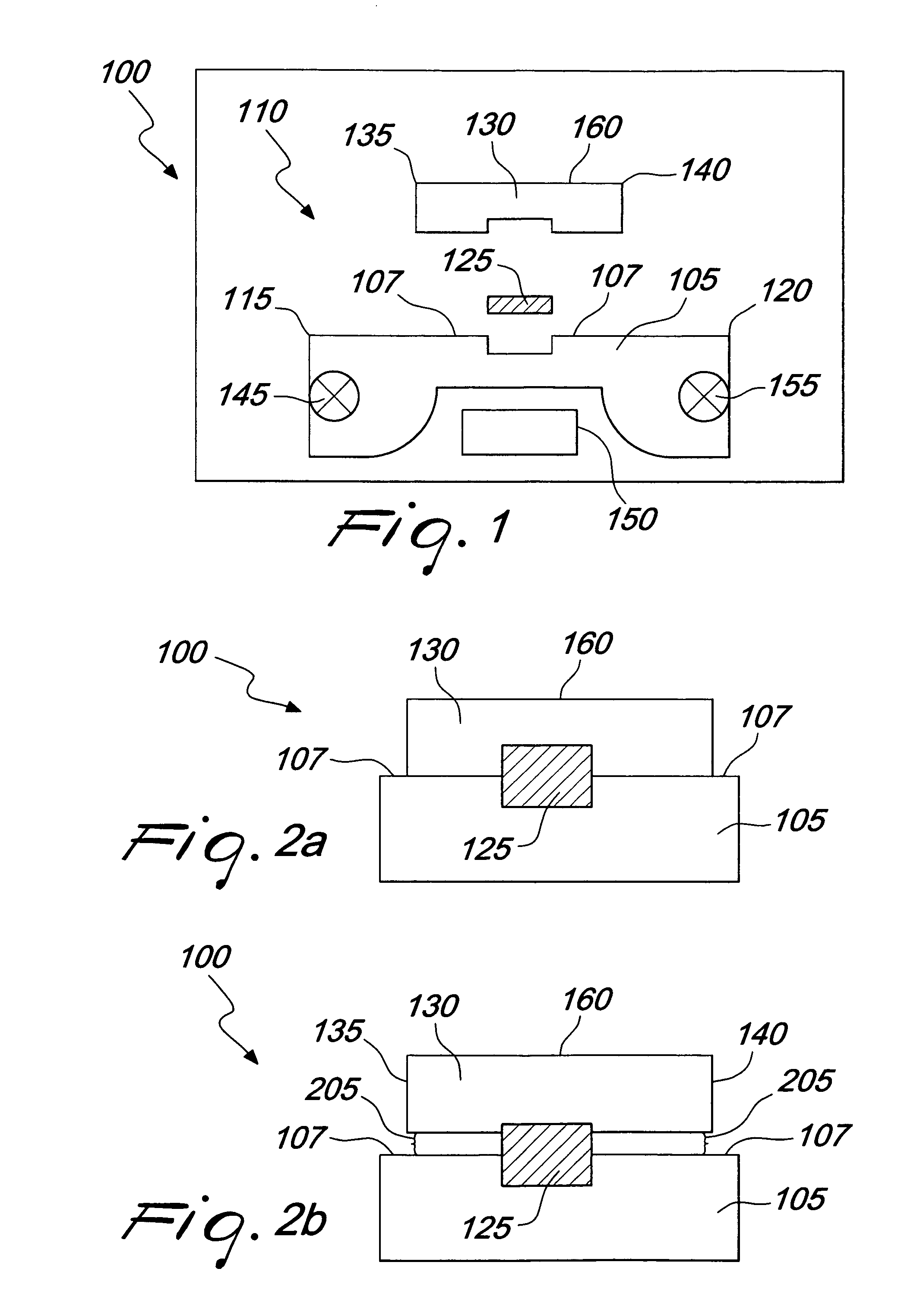
[0023]As shown in the drawings for the purposes of illustration, the invention may be embodied in apparatuses and methods for real time production line process activity, where the apparatuses and methods compensate for a limited footprint and undesirable forces arising along bends or linear portions of the assembly line to enhance overall efficiency and performance.

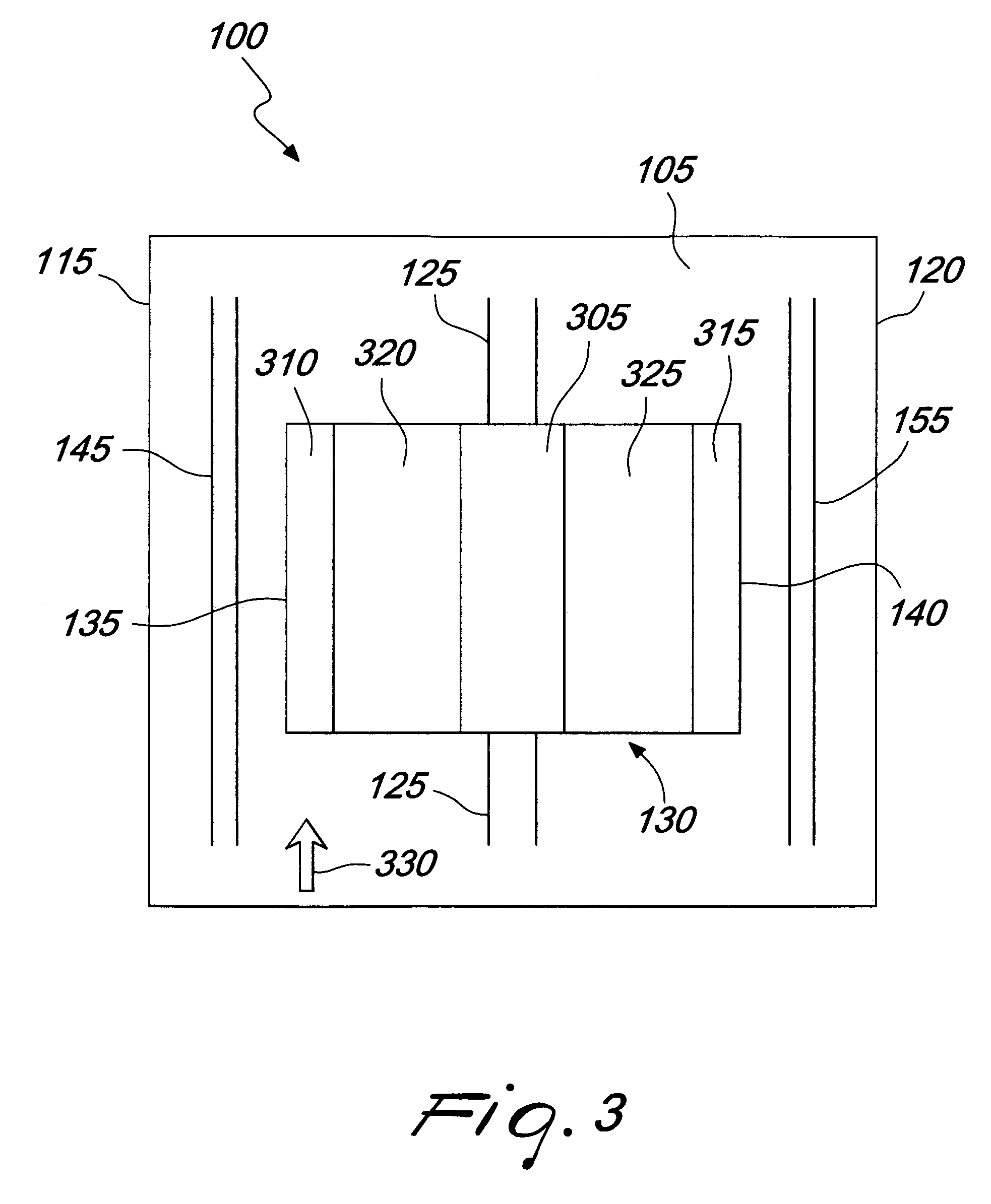
[0024]In brief overview, FIG. 1 is an exploded cross-sectional block diagram that depicts an apparatus 100 for controlling an assembly line environment in accordance with an embodiment of the invention. The system 100 typically includes one or more guides 105. Various embodiments may include more than one guide 105. Generally, multiple guides may be located side by side relative to each other. Guide 105 may include any assembly structure that holds the assembly line in place in the desired position. In various embodiments guide 105 may be made of a polymer or polymers, metal, or any combination thereof. Typically guide 10...


PUM


Abstract

Systems and methods for controlling the planarity of a conveyance element with respect to a guide while the conveyance element is in motion. This control is achieved by coupling a guide to a conveyance element where the conveyance element is held in a level position by a magnetic force. The attractive force specifically holds the edges of the conveyance element in place, so that they do not lift up or separate from the guide as the guide, by way of a chain coupling the guide to the conveyance element, carries the conveyance element through a defined path over a linear distance or around a corner in, for example, a manufacturing line environment.

Description

CROSS-REFERENCE TO RELATED APPLICATIONS[0001]This is based on and claims priority to and the benefits of U.S. patent application Ser. No. 11 / 000,965, filed Dec. 2, 2004 and Italian Patent Application TV2004A000115, filed Oct. 18, 2004. The entirety of both of these applications is hereby incorporated by reference.FIELD OF THE INVENTION[0002]The present invention relates to the development, creation, and use of a guide for controlling the movement of conveyance elements on an assembly line, and more particularly to controlling conveyance elements in a manufacturing or processing environment so that the conveyance elements remain level as they follow a path set out by the guide over a linear distance or around corners during, for example, high speed assembly line manufacturing.BACKGROUND OF THE INVENTION[0003]The design of suitable systems for moving articles from point A to point B, such as in an assembly line environment, is particularly important in the provision of industrial faci...

Claims


Application Information

Patent Timeline
Patent Type & Authority Patents(United States)
IPC IPC(8): B65G35/00
CPCB65G17/086B65G21/2009B65G2812/02851
Inventor FANDELLA, SERGIO
Owner HABASIT AG
Why Eureka
Try Eureka