Suspension device for motor vehicle

a suspension device and motor vehicle technology, applied in mechanical equipment, mechanical equipment, and wound springs, etc., can solve problems such as degrading the turning performance of the vehicle, and achieve the effect of preventing any degradation of the turning performan

Inactive Publication Date: 2006-10-05
HONDA MOTOR CO LTD
View PDF5 Cites 20 Cited by
  • Summary
  • Abstract
  • Description
  • Claims
  • Application Information

AI Technical Summary

Benefits of technology

[0007] The present invention has been accomplished under the above-mentioned circumstances, and it is an object thereof to prevent any degradation in turning performance by preventing the lower end of a coil spring of a vehicular suspension system from lifting from a spring seat when the coil spring is elongated.

Problems solved by technology

When the coil spring thus lifts from the spring seat, the spring constant of the coil spring decreases substantially, the stroke of a wheel on the inside of the turn increases, and there is a possibility that the vehicle body might rise and the tire might easily lift from the road surface, thus degrading the turning performance of the vehicle.

Method used


Image

  • Suspension device for motor vehicle
  • Suspension device for motor vehicle
  • Suspension device for motor vehicle

Examples


first embodiment

[0019]FIG. 1 to FIG. 3B show the present invention.

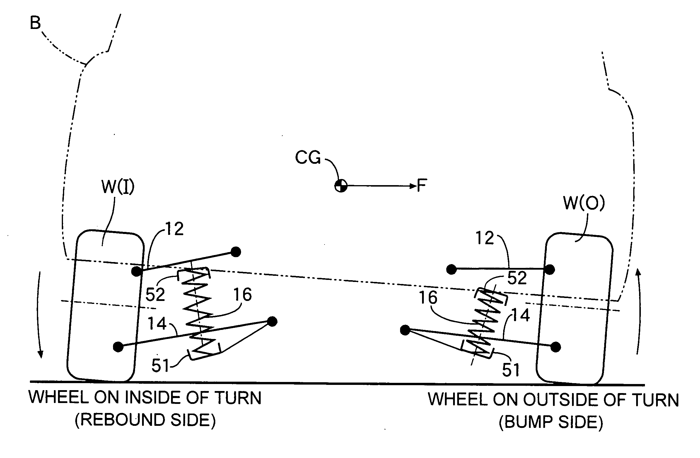
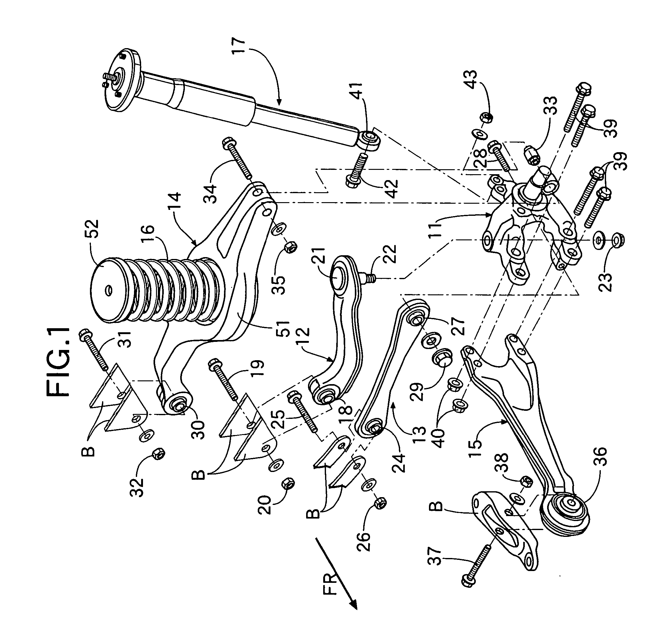
[0020] As shown in FIG. 1, a vehicular suspension system includes a knuckle 11 rotatably supporting a wheel, which is not illustrated; an upper arm 12, a front lower arm 13, a rear lower arm 14, and a trailing arm 15, which vertically movably support the knuckle 11 on a vehicle body; a coil spring 16 cushioning vertical movement of the knuckle 11; and a shock absorber 17 damping the vertical movement of the knuckle 11.

[0021] The upper arm 12 has an inner end thereof supported by a bolt 19 and a nut 20 in a bracket B on a vehicle body side via a joint 18, and has an outer end thereof supported by a bolt 22 and a nut 23 on an upper face of the knuckle 11 via a joint 21. The front lower arm 13 has an inner end thereof supported by a bolt 25 and a nut 26 in a bracket B on the vehicle body side via a joint 24, and has an outer end thereof supported by a bolt 28 and a nut 29 in a front part of the knuckle 11 via a joint 27.

[0022] The re...

second embodiment

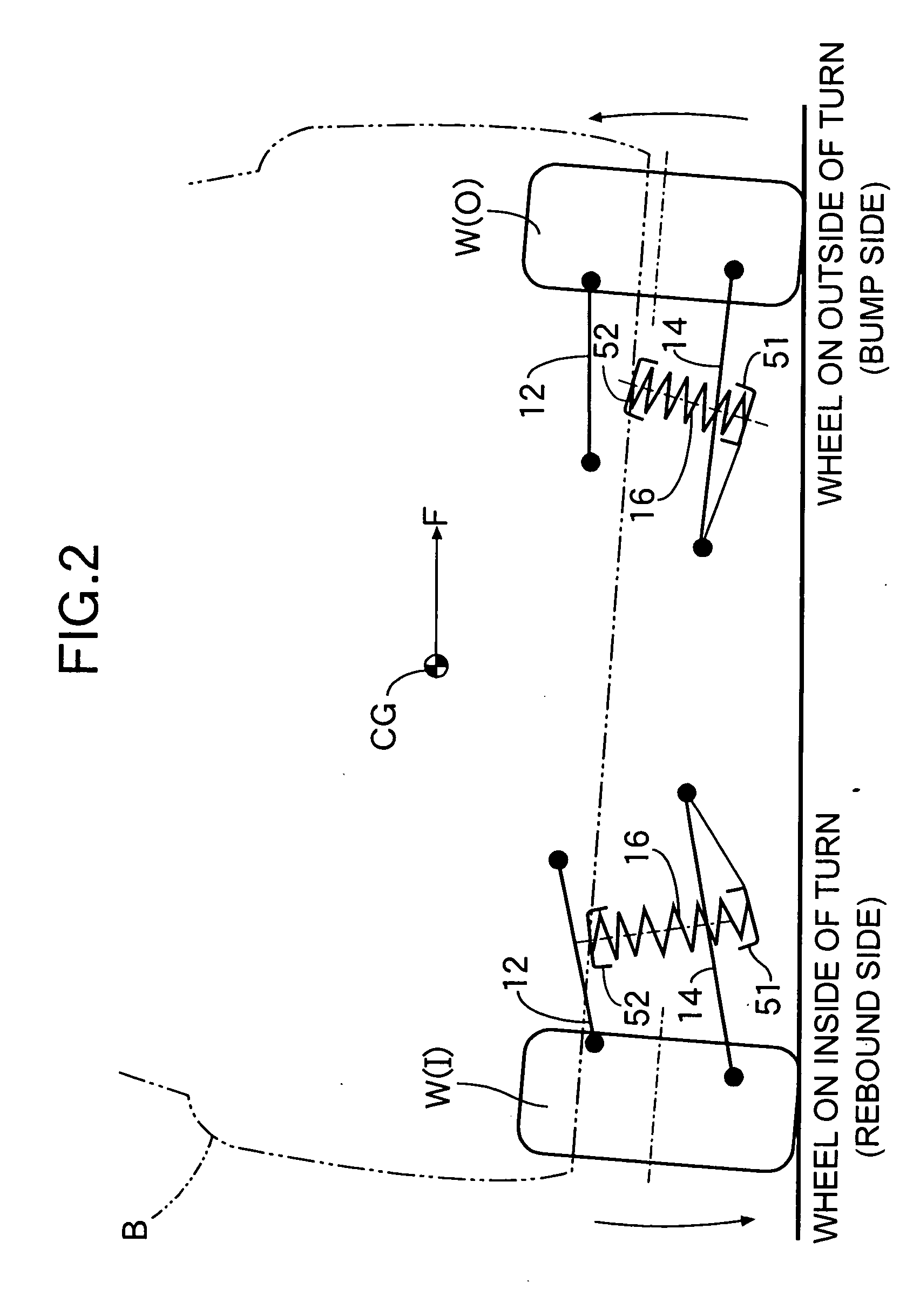
[0029] the present invention is now explained by reference to FIG. 5A and FIG. 5B.

[0030]FIG. 5A shows a suspension system in a 1 G state, in which a coil spring 16 having opposite ends thereof supported by upper and lower spring seats 51 and 52 has a middle section thereof curved inwardly in advance toward a vehicle body. When the coil spring 16 rebounds from this state as shown in FIG. 5B, the lower spring seat 51 swings downward and inward with a joint 30 as the center, the upper and lower spring seats 51 and 52 are thereby made parallel, and the coil spring 16 is elongated in a straight line. During this process, in addition to the upper and lower spring seats 51 and 52 becoming parallel to each other, by making the axes of the two spring seats 51 and 52 coincide with each other, the coil spring 16 can reliably be elongated in a straight line.

[0031] By positioning the upper and lower spring seats 51 and 52 in advance so that the coil spring 16 becomes straight at a time of rebou...


PUM


Abstract

A vehicular suspension system is provided in which the lower end of a coil spring (16) is positioned lower than a support part (30) where a suspension arm (14) is supported on a vehicle body, the lower end of the coil spring (16) is positioned on the laterally inner side of the vehicle body relative to the upper end of the coil spring (16), and when a wheel (W) rebounds and the coil spring (16) is elongated, the lower end of the coil spring (16) can therefore move along its axis. As a result, the coil spring (16) can be prevented from bending at a time of rebound, the spring constant thus increases, and the lower end of the coil spring (16) is pressed strongly against a spring seat (51) and thus prevented from lifting, thereby preventing any degradation in the turning performance. This can prevent the lower end of the coil spring of the vehicular suspension system from lifting from the spring seat when the coil spring is elongated, thus preventing any degradation in the turning performance.

Description

FIELD OF THE INVENTION [0001] The present invention relates to a vehicular suspension system in which the lower end of a coil spring is supported on a suspension arm that vertically movably supports a knuckle, and the upper end of the coil spring is supported on a vehicle body. The present invention also relates to a vehicular suspension system in which a suspension arm is arranged so that a knuckle rotates rearward when a rear wheel rebounds. BACKGROUND ART [0002] A vehicular suspension system in which a knuckle is vertically movably supported by a suspension arm, the suspension arm is connected to a vehicle body by a coil spring, and the knuckle is connected to the vehicle body by a shock absorber is known from the following Patent Document. [0003] [Patent Document][0004] Japanese Utility Model Registration Publication No. 2605811 [0005] When a vehicle turns, a centrifugal force directed toward the outside of the turn acts on the center of gravity of the vehicle, and since the cen...

Claims


Application Information

Patent Timeline
Patent Type & Authority Applications(United States)
IPC IPC(8): B60G3/20B60G7/00B60G11/14B60G11/16F16F1/12
CPCB60G3/20B60G11/14B60G11/16B60G2204/1244B60G2202/12B60G2204/124B60G2200/182
Inventor ORIMOTO, YUKIHIROKUROSU, NORIKAZU
Owner HONDA MOTOR CO LTD
Why Eureka
Try Eureka