Bone conduction earphone

a bone conduction earphone and earphone technology, applied in the direction of deaf-aid sets, electrical transducers, transducer details, etc., can solve the problems of limited magnetic force generated by the conventional bone conduction earphone, inability to achieve quick and accurate response, and limit the improvement of sound quality and power consumption of audio devices, so as to reduce manufacturing costs, the effect of smooth transmission and simplified structur

Active Publication Date: 2009-12-10
COSMOGEAR
View PDF1 Cites 19 Cited by
  • Summary
  • Abstract
  • Description
  • Claims
  • Application Information

AI Technical Summary

Benefits of technology

[0016]Since the through holes continuous with each other are provided in the respective center positions of the diaphragm, the substrate, the first magnet, and the first plate, and the respective members are integrally connected by the securing pin penetrating the through holes, the structure is simplified, whereby reduction of manufacturing cost can be achieved.
[0017]Since the diaphragm is configured with the center part attached to the substrate, the peripheral part attached to the frame, and the plurality of connection parts provided radially between the center part and the peripheral part, and the connection part is formed with a bend part bended in a...

Problems solved by technology

However, magnetic forces generated by the conventional bone conduction earphones are limited, whereby a quick and accurate response cannot be expected unless an accord...

Method used


Image

  • Bone conduction earphone
  • Bone conduction earphone
  • Bone conduction earphone

Examples


Embodiment Construction

[0024]Next, an embodiment of the present invention will be described in detail based on the accompanying drawings.

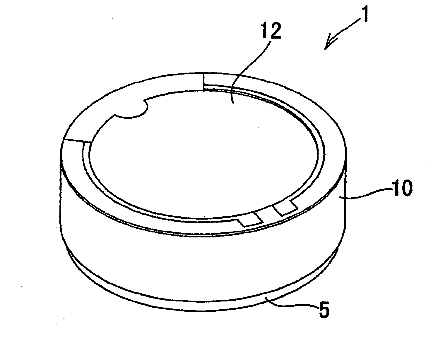
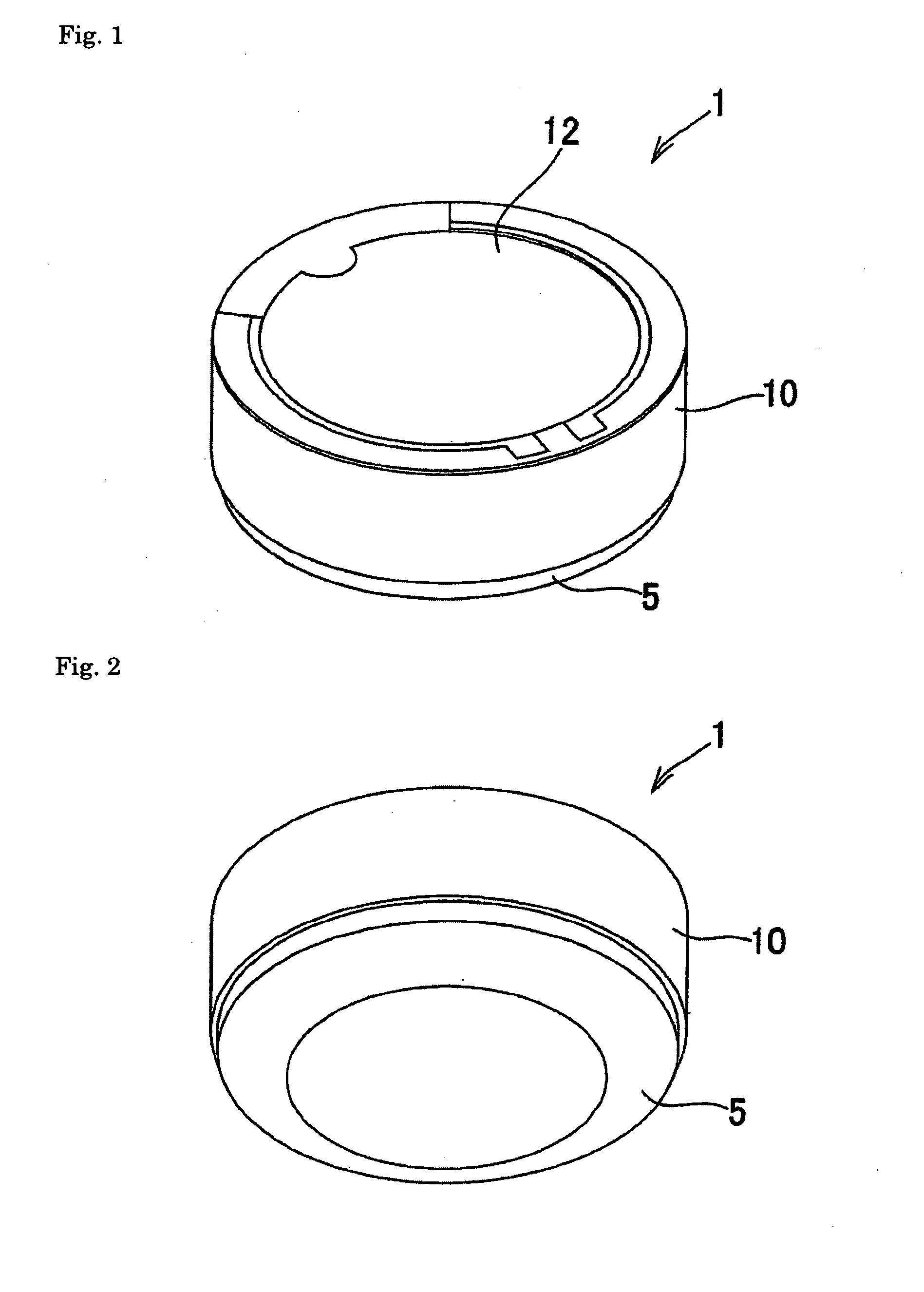
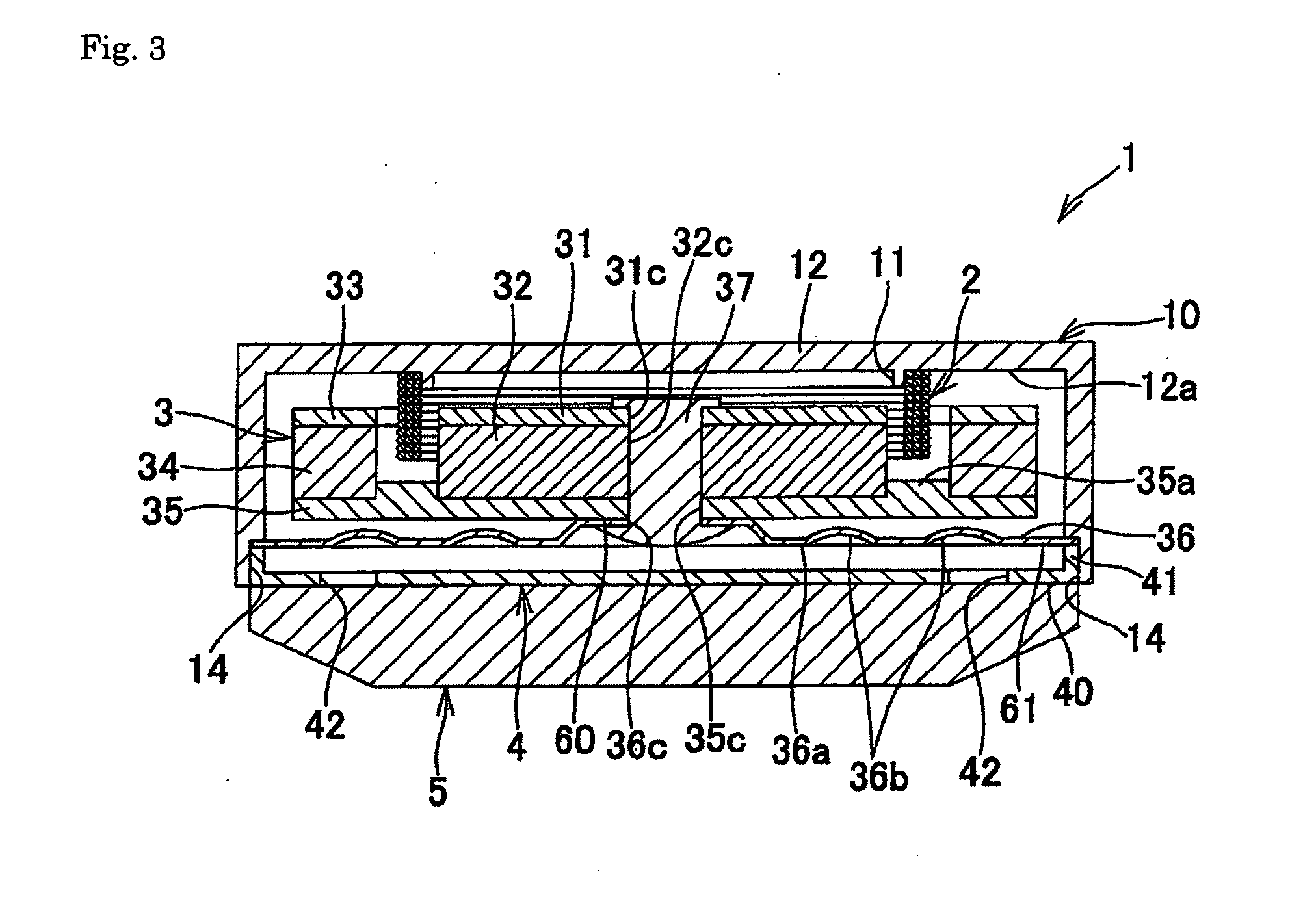
[0025]FIGS. 1 to 5 show a bone conduction earphone according to a representative embodiment of the present invention. In the drawings, reference numeral 1 denotes the bone conduction earphone, 2 denotes a voice coil, 3 denotes a vibration part, 4 denotes a cap, and 5 denotes a vibration transmission cushion. The bone conduction earphone 1 of the present invention is configured with a frame 10, the voice coil 2, the vibration part 3, the cap 4, and the vibration transmission cushion 5.

[0026]As shown in FIGS. 3 to 5, the bone conduction earphone 1 of the present invention includes the vibration part 3 including a first magnet 32 and a second magnet 34 which coaxially secure the voice coil 2 on an inner surface 12a of an upper wall 12 of the cylinder-shaped frame 10 having an open lower part and are located in an inner side region and an outer side region of the voice coil ...


PUM


Abstract

A bone conduction earphone in which a large magnetic force can be generated and which can achieve improvement of sound quality and reduction of power consumption is provided. A vibration part 3 is provided to include a first magnet 32 and a second magnet 34, which coaxially secure a voice coil 2 on an inner surface 12a of an upper wall 12 of a cylinder-shaped frame 10 having an open lower part and are located in an inner side region and an outer side region of the voice coil 2, and a diaphragm 36 which connects the first magnet 32 and the second magnet 34 to the frame 10. A vibration transmission cushion 5 is provided to a lower part of the frame 10 in order to transmit a vibration of the voice coil 2 and the vibration part 3 to a human body.

Description

BACKGROUND OF THE INVENTION[0001]1. Field of the Invention[0002]The present invention relates to a bone conduction earphone, and more specifically relates to a bone conduction earphone which can quickly and accurately reflect a small change of electric current in a bone conducted vibration.[0003]2. Description of the Background Art[0004]Normally, a vibration of sound conducted through air is transmitted to an eardrum inside an ear. There are three bones (ossicles) inside the eardrum, and a vibration of the eardrum is transmitted to a screw-like cochlea via the bones. The cochlea contains lymph, and a vibration of the lymph is transmitted to the auditory nerve as electric signals, whereby a brain recognizes the sound. On the other hand, in a bone conduction, the process of the vibration travelling through the eardrum and the ossicles in the mechanism described above is omitted. That is, the vibration of sound is directly sent to the cochlea via a skull, whereby even a hearing-impaire...

Claims


Application Information

Patent Timeline
IPC IPC(8): H04R25/00H04R13/00
CPCH04R2460/13H04R1/1075
Inventor NAKATANI, HIDENORI
Owner COSMOGEAR
Why Eureka
Try Eureka