Linear vibrator

a linear vibrator and vibrating plate technology, applied in mechanical vibration separation, dynamo-electric machines, electrical apparatus, etc., can solve the problems of increasing assembly process time, reducing assembly accuracy, and reducing assembly cost, so as to improve assembly accuracy and reduce production cost. , the effect of simplifying the manufacturing process

Inactive Publication Date: 2010-11-04
SAMSUNG ELECTRO MECHANICS CO LTD
View PDF8 Cites 20 Cited by
  • Summary
  • Abstract
  • Description
  • Claims
  • Application Information

AI Technical Summary

Benefits of technology

[0016]The present invention has been made in an effort to provide a linear vibrator which enhances the assembly accuracy, reduces the production cost, and simplifies the manufacturing process.
[0017]The present invention provides a linear vibrator which can minimize contact of a vibration unit with a coil or casing.
[0018]The present invention provides a linear vibrator which can increase magnetic force generated between the coil and a magnet.
[0023]In the linear vibrator, a damper member may be further provided on the bracket below the vibration unit to prevent the vibration unit from coming into contact with the bracket when the vibration unit linearly vibrates.

Problems solved by technology

However, in the vibration generating unit having this structure, when the brush passes through a gap between segments of the commutator, mechanical friction, electric sparks or abrasion is induced, thus creating impurities, such as black powder, thereby reducing the lifetime of the vibration generating unit.
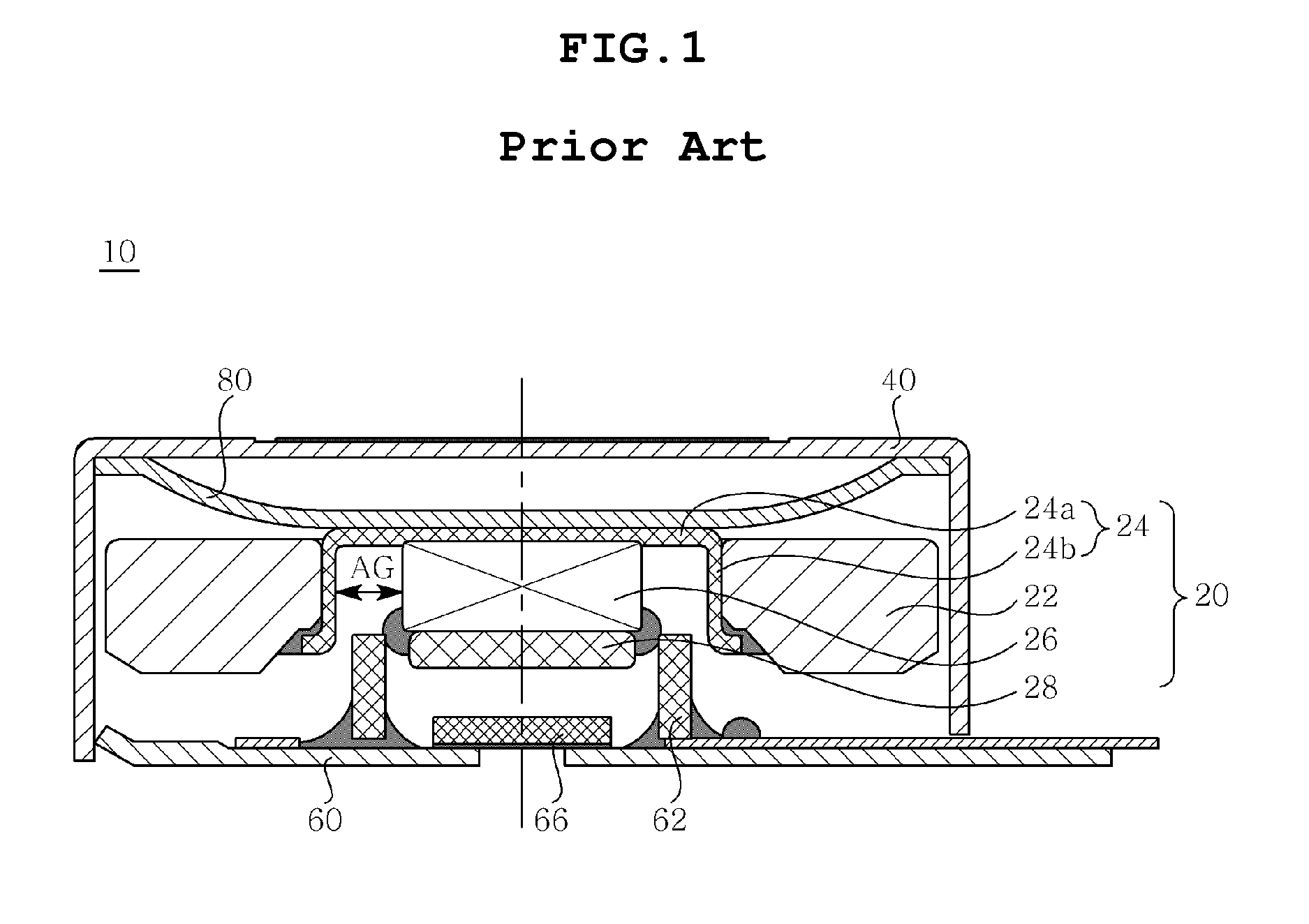
Hence, the assemblability is reduced, thus increasing the assembly process time.
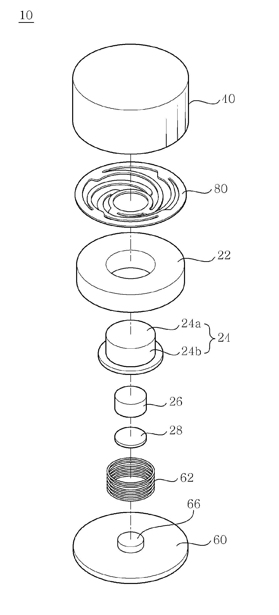
Furthermore, since the weight 22 which has a relatively high specific gravity and is expensive to manufacture must be formed in a complex shape, it is difficult to machine the weight 22 and a loss of material when machining is increased.
It is not easy to form the insert hole through the weight 22, and a loss of material corresponding to the size of the insert hole results from the process as well.
Therefore, the magnetic force is reduced, thus causing undesirable fine vibrations.
Thereby, it is difficult to ensure reliable vibration characteristics.

Method used


Image

  • Linear vibrator
  • Linear vibrator
  • Linear vibrator

Examples


Embodiment Construction

[0031]Reference now should be made to the drawings, in which the same reference numerals are used throughout the different drawings to designate the same or similar components. In the following description, when it is determined that the detailed description for the conventional function and conventional structure confuses the gist of the present invention, the description may be omitted. Furthermore, the terms and words used in the specification and claims are not necessarily limited to typical or dictionary meanings, but must be understood to indicate concepts selected by the inventor as the best method of illustrating the present invention, and must be interpreted as having meanings and concepts adapted to the scope and sprit of the present invention for understanding the technology of the present invention.

[0032]Hereinafter, an embodiment of the present invention will be described in detail with reference to the attached drawings.

[0033]FIG. 3 is a sectional view of a linear vibr...


PUM


Abstract

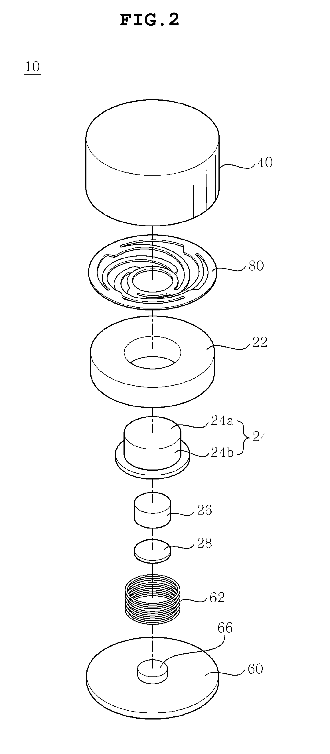
The present invention provides a linear vibrator which can enhance the assembly accuracy and prevent a vibration unit from coming into direct contact with a coil or a casing. The linear vibrator includes a vibration unit, a casing, a bracket and a spring member. The vibration unit includes a plate yoke which has a weight on an upper surface thereof, and an annular magnet which is provided on the plate yoke and surrounds the weight. The casing has an internal space for receiving the vibration unit therein. The bracket is coupled to the lower end of the casing. A cylindrical coil is provided on the bracket such that the vibration unit linearly vibrates in the cylindrical coil. The spring member is provided in the upper end of the casing to elastically support the vibration unit such that the vibration unit linearly vibrates.

Description

CROSS REFERENCE TO RELATED APPLICATION[0001]This application claims the benefit of Korean Patent Application No. 10-2009-0038906, filed May 4, 2009, entitled “Linear vibrator”, which is hereby incorporated by reference in its entirety into this application.BACKGROUND OF THE INVENTION[0002]1. Technical Field[0003]The present invention relates to a linear vibrator.[0004]2. Description of the Related Art[0005]Generally, portable electronic devices, such as mobile phones, game players, mobile information terminals, etc., have various vibration generating units to prevent noise therefrom from disturbing other people. Particularly, such a vibration generating unit is installed in a cellular phone and used as a mute signal reception indicating unit (including haptic vibration). Recently, in accordance with the trend to provide a small and slim cellular phone, a reduction in the size and an increase in the function of a vibration generating unit installed in the cellular phone are also requ...

Claims


Application Information

Patent Timeline
Patent Type & Authority Applications(United States)
IPC IPC(8): H02K33/02
CPCH02K33/18B06B1/04
Inventor JEON, YOUNG JAE
Owner SAMSUNG ELECTRO MECHANICS CO LTD
Why Eureka
Try Eureka