Position detecting device

a technology of position indicator and detecting electrode, which is applied in the direction of instruments, transmission systems, computing, etc., can solve the problems of lowering detection accuracy and inability to obtain sufficient electromotive force in the resonant circuit of position indicator, so as to prevent or suppress the generation of eddy current in the detection electrode

Active Publication Date: 2012-07-24
WACOM CO LTD
View PDF11 Cites 33 Cited by
  • Summary
  • Abstract
  • Description
  • Claims
  • Application Information

AI Technical Summary

Benefits of technology

[0009]There has been proposed a position detecting device in which both the electromagnetic induction type detecting method and electrostatic capacity type detecting method can be used in a common input area. In such a position detecting device, by superimposing an electromagnetic induction type detection section and an electrostatic capacity type detection section onto one another, two different input methods can be performed in the common input area without increasing the size of the device.
[0011]In such a position detecting device, a magnetic flux G generated by a coil 27 of a position indicator 2 is perpendicular to the detection electrode 201 of the electrostatic capacity type detection section. Thus, the magnetic flux G generates an eddy current I in the detection electrode 201. The eddy current I in the detection electrode 201 generates a new magnetic flux which has a direction so as to attenuate the magnetic flux G generated by the position indicator 2 (i.e., the direction of the new magnetic flux is opposite to the direction of the magnetic flux G). Since the new magnetic flux attenuates the magnetic flux G from the position indicator 2, detection of the magnetic flux G by the electromagnetic induction type detection section is reduced. As a result, detection accuracy is lowered.
[0014]In view of the aforesaid problems, it is an object of the present invention to provide a position detecting device where not only the degradation of the detection accuracy of the first detection section (e.g., an electrostatic capacity type detection section) can be prevented or suppressed, but also the degradation of the detection accuracy of the second detection section (e.g., an electromagnetic induction type detection section) can be prevented or suppressed.
[0016]With the position detecting device according to the present embodiment, by forming at least one slit in the detection electrode of the first detection section (an electrostatic capacity type detection section), the eddy current generated in the detection electrode can be prevented or suppressed. Thereby the degradation of the detection accuracy of the second detection section (an electromagnetic induction type detection section) can be prevented or suppressed.

Problems solved by technology

As a result, detection accuracy is lowered.
As a result, sufficient induced electromotive force cannot be obtained in the resonant circuit of the position indicator 2.

Method used


Image

  • Position detecting device
  • Position detecting device
  • Position detecting device

Examples


Embodiment Construction

)

[0030]Embodiments of a position detecting device according to the present invention will be described below with reference to FIGS. 1 to 11. In the attached drawings, like components are denoted by like numerals. While illustrative embodiments will be illustrated and described, it will be appreciated that various changes can be made therein.

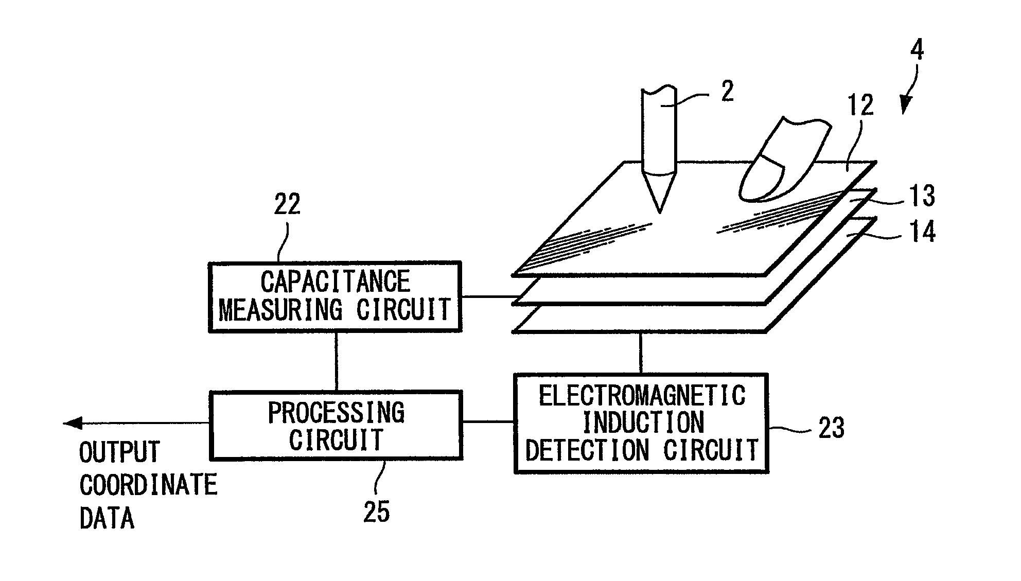
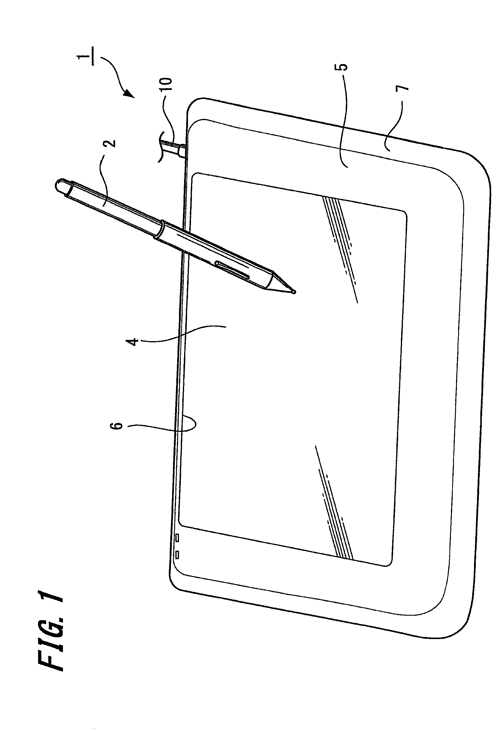
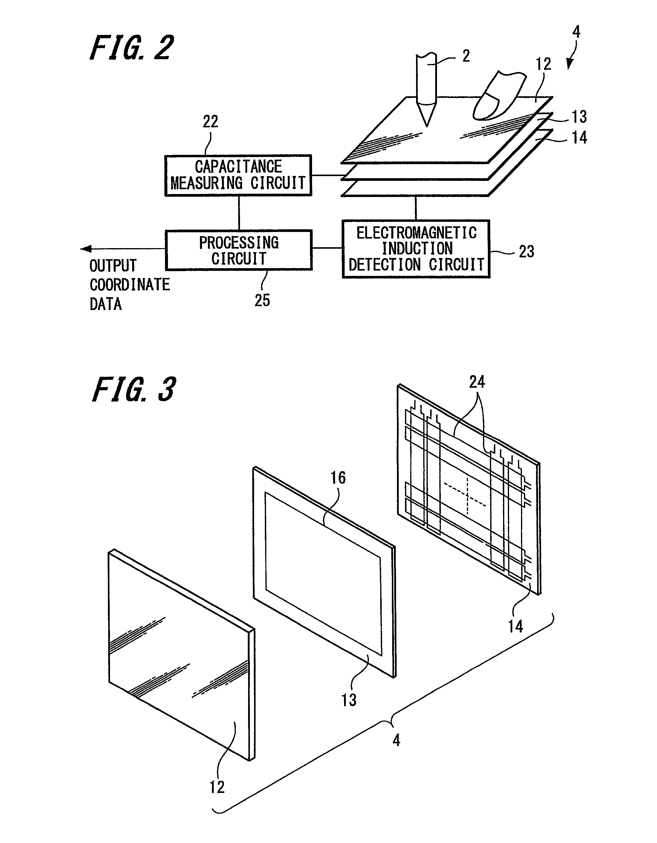
[0031]Firstly, a configuration of a position detecting device 1 according to one embodiment of the present invention will be described below with reference to FIG. 1. As shown in FIG. 1, the position detecting device 1 is connected to an external device (not shown) such as a personal computer, a PDA (Personal Digital Assistant) or the like through a cable 10. In such a manner, the position detecting device 1 is used as an input device of the external device. Note that, although not shown in the drawings, the position detecting device 1 may also be incorporated into a personal computer or the like.

[0032]Referring additionally to FIG. 4, the posit...


PUM


Abstract

A position detecting device includes a position indicator (2), a first detection section (13) (e.g., an electrostatic capacity type detection section) having a substantially flat shape, and a second detection section (14) (e.g., an electromagnetic induction type detection section). The position indicator (2) has a coil (27). The first detection section (13) has, on one surface thereof, detection electrodes (15) for detecting a capacitance between itself and a human body part. The second detection section (14) is provided with loop coils (24) for detecting a magnetic flux G. Further, each of the detection electrodes (15) has a substantially flat shape, and is provided with at least one slit (19) extending from the outer edge to the inside. With such a configuration, not only can degradation of detection accuracy of the first detection section be prevented or suppressed, but also degradation of detection accuracy of the second detection section can be prevented or suppressed.

Description

CROSS REFERENCES TO RELATED APPLICATIONS[0001]The present application claims priority under 35 U.S.C. §119 from Japanese Patent Application JP 2007-340099 filed in the Japanese Patent Office on Dec. 28, 2007, the entire contents of which are incorporated herein by reference.BACKGROUND OF THE INVENTION[0002]1. Field of the Invention[0003]The present invention relates to a position detecting device in which an electrostatic capacity type detection section and an electromagnetic induction type detection section are superimposed on each other, so that a position indicated by either a position indicator or a human body part (e.g., a finger) can be detected.[0004]2. Description of the Related Art[0005]Conventionally, a position detecting device has been used as a device for performing position input in an information-processing device such as a personal computer. In such a position detecting device, a pointing operation or a handwriting input operation such as handwriting a character or h...

Claims


Application Information

Patent Timeline
Patent Type & Authority Patents(United States)
IPC IPC(8): G09G5/00
CPCG06F3/03545G06F3/044G06F3/046G06F2203/04111G06F3/0446G06F3/0448
Inventor MATSUBARA, MASAKI
Owner WACOM CO LTD
Why Eureka
Try Eureka