Method and system for providing a magnetic recording transducer having a hybrid moment pole

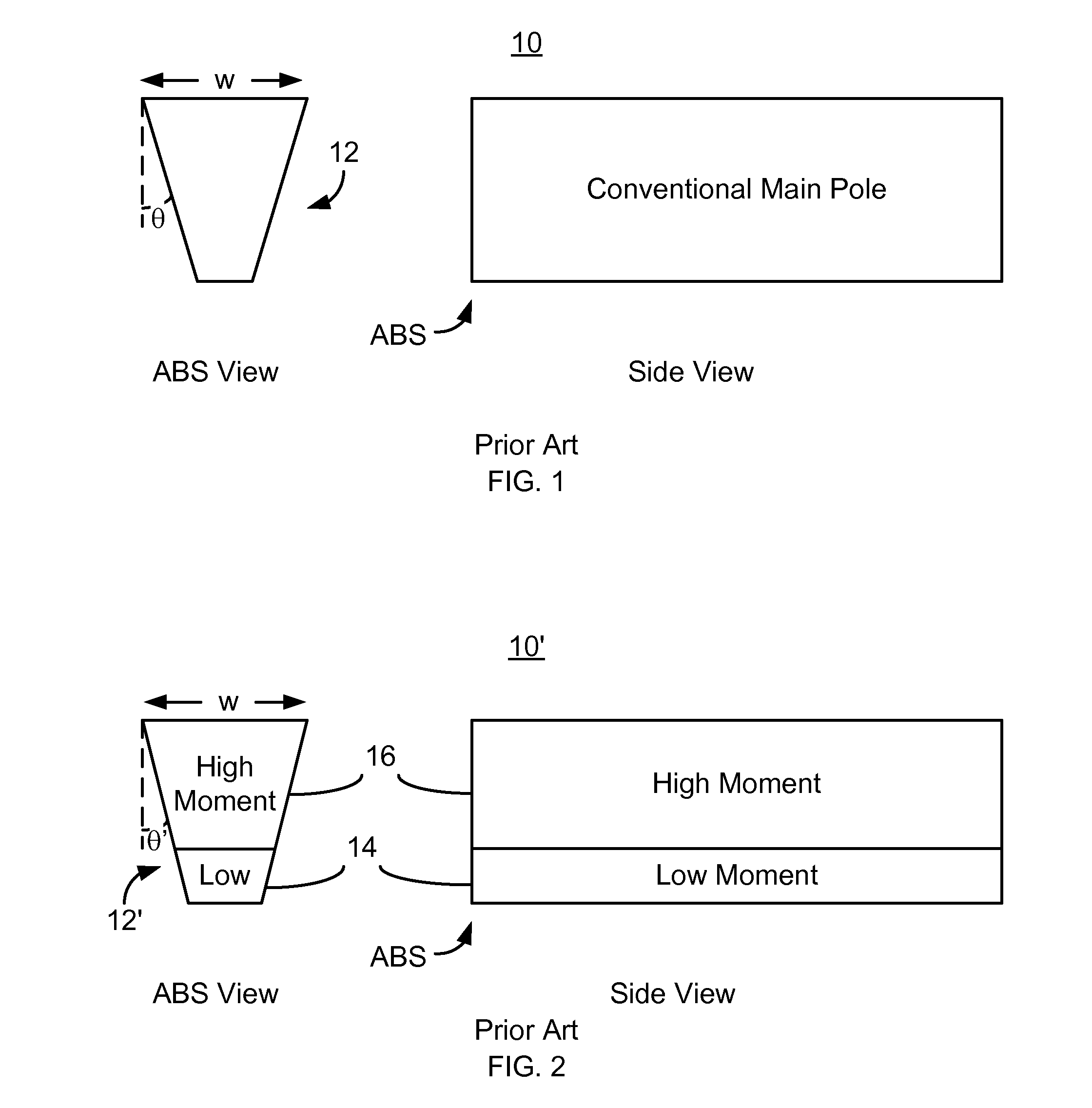
a technology of magnetic recording transducer and moment pole, which is applied in the field of providing a magnetic recording transducer having a hybrid moment pole, can solve the problems of inability to deliver as high a magnetic field, the main pole b>10/b> may be difficult to fabricate, and the writeability may suffer

Active Publication Date: 2012-07-24
WESTERN DIGITAL TECH INC
View PDF34 Cites 153 Cited by
  • Summary
  • Abstract
  • Description
  • Claims
  • Application Information

AI Technical Summary

Benefits of technology

[0007]A method and system provide a magnetic transducer that includes an air-bearing surface (ABS). The magnetic transducer includes an underlayer and a main pole residing on the underlayer. The main pole includes a front and a rear. The front resides at the ABS, while the rear is distal from the ABS. The main pole also includes a first portion having a first magnetic moment and a second ...

Problems solved by technology

Such a conventional main pole 10 may be difficult to fabricate.
Although the conventional main pole 10′ may be easier to fabricate at higher recording densities, writeability may suffer.
The conventional main pole 10′ may be u...

Method used


Image

  • Method and system for providing a magnetic recording transducer having a hybrid moment pole
  • Method and system for providing a magnetic recording transducer having a hybrid moment pole
  • Method and system for providing a magnetic recording transducer having a hybrid moment pole

Examples


Embodiment Construction

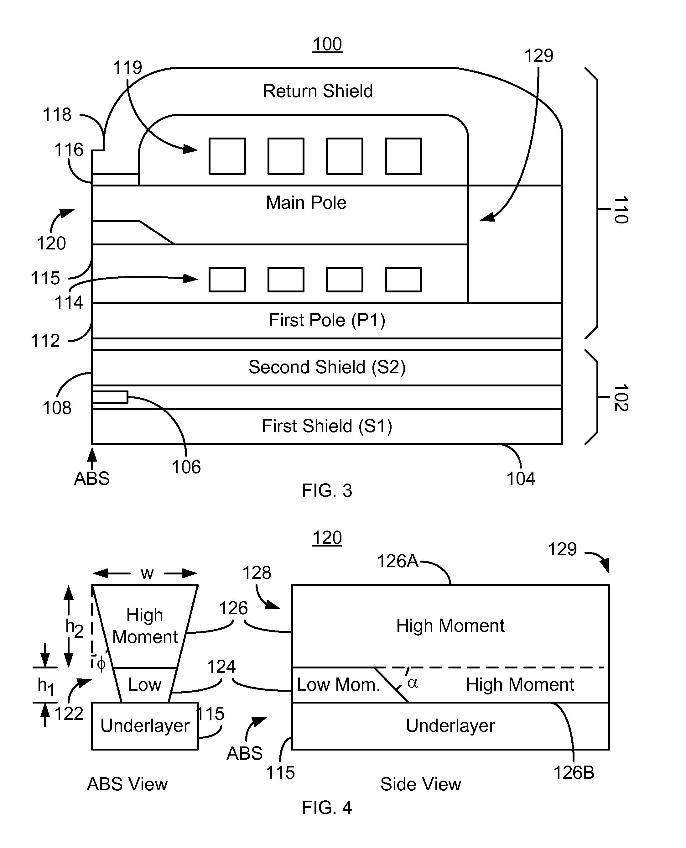
[0023]FIG. 3 depicts a side view of an exemplary embodiment of a magnetic recording head 100. For clarity, FIG. 3 is not drawn to scale. In addition, seed and / or capping layers are not shown. The magnetic recording head 100 may reside on a slider and be part of a disk drive. The magnetic recording head 100 shown is a merged head including a read transducer 102 and a write transducer 110. In another embodiment, the magnetic head 100 may include only the magnetic transducer 110. The read transducer 102 includes first and second shields 104 and 108 as well as a read sensor 106 between the shields 104 and 108. The magnetic transducer 110 shown is a PMR transducer and includes a first pole 112, coils 114 and 119, write gap 116, return shield 118, and main pole 120. The main pole 120 resides on an underlayer 115. In another embodiment, portions of the magnetic transducer 110 may be omitted. For example, a single coil 114 or 119 may be used. Similarly, the return shield 118 might be omitte...


PUM


Abstract

A method and system provide a magnetic transducer that includes an air-bearing surface (ABS). The magnetic transducer includes an underlayer and a main pole residing on the underlayer. The main pole includes a front and a rear. The front resides at the ABS, while the rear is distal from the ABS. The main pole also includes a first portion having a first magnetic moment and a second portion having a second magnetic moment. The first portion has a front face at the ABS and terminates between the ABS and the rear of the main pole. A part of the second portion resides on the first portion, while another part of the second portion resides between the first portion of the main pole and the rear of the main pole. The first magnetic moment is less than the second magnetic moment.

Description

BACKGROUND[0001]FIG. 1 depicts air-bearing surface (ABS) and side views of a conventional main pole 10 for a conventional magnetic recording head. The conventional magnetic recording head may be a perpendicular magnetic recording (PMR) head. The conventional magnetic recording head typically includes a conventional read transducer (not shown) and a conventional write transducer (not shown). The conventional main pole 10 includes sidewalls 12 at an angle, θ, from vertical. For the conventional main pole 10 to be used, the angle, θ, is greater than zero degrees. For example, angles in the range of eight to nine degrees may be used. The width, w, of the main pole corresponds to the track width of the conventional main pole 10. The conventional main pole 10 includes a high moment material, such as CoFe having a moment of two Tesla or higher.[0002]Although the conventional main pole 10 functions, the trend in magnetic recording heads is to higher recording densities and, therefore, lower...

Claims


Application Information

Patent Timeline
IPC IPC(8): G11B5/23
CPCG11B5/3116G11B5/1278G11B5/3163
Inventor TRAN, UTBAI, ZHIGANG
Owner WESTERN DIGITAL TECH INC
Why Eureka
Try Eureka